background image

860106368 

Instruction Sheet 


www.commscope.com 


Page 8 of 12 


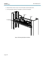
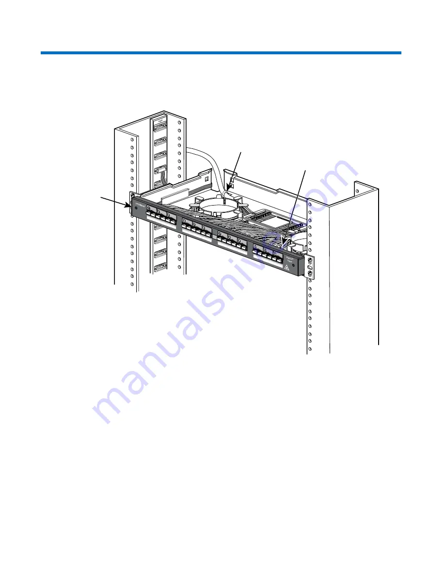
5.  Dress the fibers as shown in Figure 7 and route the slack around the storage drums. 

6.  Connect the pigtail connectors to the adapters on the back of the faceplate. 


Figure 7 Positioning the Splices and Fibers 

Pigtail

Cable tie

Faceplate


Summary of Contents for iP-600A-12-CSC-SMF

Page 1: ...ion 6 2 or later We recommend that you upgrade the System Manager software to Version 6 2 or a later version before you install the shelf System Manager will automatically upgrade the iPatch Manager software Ordering information is listed below Material ID Part No Description 760005595 iP 600A 12 SC MMF 600A fixed multimode intelligent fiber shelf SC 12 port duplex 760080887 iP 600A 12 CSC SMF 600...

Page 2: ... ties 3 Fiber type labels 8 labels each sheet 1 Double sided tape 6 inches 15 2cm for mounting splice organizers 1 Instruction sheet Separately Orderable Components Material ID Part No Description 700006257 1AF1 16LG Fusion splice organizers 700006281 1AMF1 6LG Mass fusion splice organizers 700006240 1AM1 12LG Mechanical splice organizers 1U 19 Patch Cord Trough Specifications Fiber Optic Interfac...

Page 3: ...ch has a preferential bend axis Use caution to avoid kinking trunk cables iPatch high density fiber MPO adapters are equipped with protective dust caps installed in the front of all adapters Prior to installation clean the trunk cable and jumper connectors per the manufacturer s recommendations All wiring that connects to this equipment must meet applicable local and national building codes and ne...

Page 4: ...f slide the plastic cover off the shelf 2 Mount the shelf in the rack using the four 12 24 x 3 8 inch screws provided Figure 2 Figure 2 Installing the Shelf in the Rack 3 Connect the panel bus jumper to the nearest connector on the panel bus Figure 3 Note The connector is keyed The polarized tab on the jumper connector fits into the opening in the header connector on the panel bus Important Make s...

Page 5: ...he Cable for Splicing or Termination Preparing the Cable for Splicing or Termination Whether you are splicing or terminating the fiber optic cable prepare the cable as shown in Figure 4 Prepare the fiber optic cable for connection to the faceplate either by splicing or terminating the cable For instructions see Splicing and Installing the Cable on page 6 or Terminating and Installing the Cable on ...

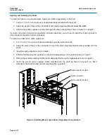
Page 6: ...olders provided To install four mass fusion splice organizers 1 Cut a 3 inch 7 5cm piece of double sided tape provided with the shelf 2 Apply the piece of tape to the underside of one of the splice organizer holders also provided with the shelf 3 Insert two splice organizers into the holder 4 Affix the holder and splice organizers to the shelf approximately in the position shown in Figure 5 5 Afte...

Page 7: ...l by untangling them and laying them out flat 3 Using the splicing materials appropriate for the type of splices you are making splice the incoming buffered fibers to the pigtail 4 For fusion splices use your fingers to place the splices in the splice organizers ordered separately in the recommended sequence shown in Figure 6 Note The numbers shown in Figure 6 do not appear on the actual splice or...

Page 8: ...Page 8 of 12 5 Dress the fibers as shown in Figure 7 and route the slack around the storage drums 6 Connect the pigtail connectors to the adapters on the back of the faceplate Figure 7 Positioning the Splices and Fibers Pigtail Cable tie Faceplate ...

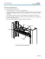
Page 9: ...his purpose Position the cable so that the tie is on the jacket about 1 inch 2 5cm from the edge of the jacket 3 Affix the adhesive backed wire retainers to the shelf approximately in the position shown in Figure 8 4 Route the buffered fibers through the wire retainers and around the storage drums to the adapters on the back of the faceplate Figure 8 5 Connect the terminated fibers to the adapters...

Page 10: ...hich is made of clear flame retardant plastic slides on and off the shelf To install the cover Slide the cover through the flanges on the shelf until the cover reaches the back wall of the shelf Figure 9 Important Dust covers are installed in the ports to protect the fibers connected to the back of the faceplate Do not remove the dust cover from a port until you connect a patch cord to that port I...

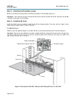
Page 11: ...arter turn in either direction Figure 10 When unlatched the screwdriver blade is horizontal Important Do not use a screwdriver with a flared blade even if it fits into the latch hole It can damage the faceplate 3 Repeat Step 2 for the other latch Figure 10 4 Holding the faceplate a couple of inches away from the shelf disconnect the panel bus jumper from the left side of the back of the faceplate ...

Page 12: ...r is firmly connected to the back of the faceplate The connector is keyed The polarized tab on the panel connector fits into the opening in the header connector on the back of the faceplate 3 Holding the faceplate in position against the shelf insert a 1 8 inch 3mm straight blade screwdriver into one of the latch holes in the front of the faceplate and rotate the latch one quarter turn in either d...

Reviews: