


408- 4457
Rev
J
12
of 16
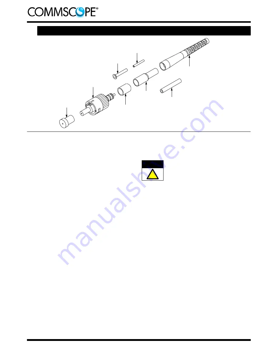
5.4.
900-
m
m Easy Strip or Semi- Tight Buffered Fiber
Connector
Assembly
Plunger
Protective
Cap
Strain
Relief
Crimp
Eyelet
Inner
Eyelet
Small
Tubing
Kit Components Required
(Discard Other Components)
Clear
Tubing
Connector kit is shipped with these installed onto connector
assembly. Keep them in place until ready for assembly.
Ferrule
Protective
Cover
A. Preparing 900-
m
m Easy Strip or Semi- Tight
Buffered Fiber
(Figure 12)
1. Place the inner eyelet, small end first, inside the
clear tubing so that the flange ofi nner eyelet is
against the end of the tube. See Figure 12,
Detail A.
2. Slide the strain relief (long), clear tubing (with
inner eyelet inside), and crimp eyelet onto the
cable. See Figure 12, Detail B.
3. Remove the ferrule protective cover and the
plunger protective cap from the connector
assembly. Keep the cover; discard the cap.
4. Insert the small (white) tubing into the connector
plunger until the tubing bottoms. See Figure 12,
Detail C.
5. Push the connector into the holder of the cable
holder with the ferrule protective cover facing
outward. Make sure that the connector butts
against the lip of the arm of the cable holder. See
Figure 12, Detail D.
6. Slide the fiber into the channel marked
“BUFFER” on the cable holder. Make sure that the
tip of the fiber butts against the end of the channel.
See Figure 12, Detail D.
7. Mark the fiber at each cross--slot of the channel.
See Figure 12, Detail D. Also, place a mark on the
buffer at the end of the channel. Remove the fiber
from the channel.
8. Using the strip tool, strip the 250--
m
m fiber
coating and buffer back to the first mark. It is
recommended holding the tool at an angle to the
fiber and stripping the coating in three sections.
See Figure 12, Detail E. Clean the fiber with
an alcohol fiber wipe to remove the fiber coating
residue.
Before using the strip tool, make sure that the “V”
opening is clean. Ifi t is not clean, the fiber could
break. Only use isopropyl alcohol to clean the
tool.
9. Using the strip tool, apply slightly less pressure
than when stripping 125--
m
m fiber, and strip the
buffer only (leave the 250--
m
m fiber coating in
place) to the second mark. Practice this first.
10. Mark the 250--
m
m fiber coating at the shoulder
of the 900--
m
m buffer. Strip the buffer to the third
mark.
B. Cleaving
(Figure 13)
1. Open the fiber clamp of the fiber optic cleaver.
Press the button, and slide the carriage back
(toward the fiber clamp). Then move the fiber slide
back until it stops.
2. Place the stripped fiber into the slot so that the
end of the buffer is at the 8--mm marking. See
Figure 13, Detail A.
3. While applying pressure on the buffer, carefully
slide the fiber slide forward (toward the carriage)
until it stops. See Figure 13, Detail B.
4. Gently close the fiber clamp, and slide the
carriage forward. DO NOT touch the button while
sliding the carriage. See Figure 13, Detail C.
5. Open the fiber clamp, and move the fiber slide
back until it stops.
6. Remove the cleaved fiber, and properly dispose
of the scrap fiber.
CAUTION
!


