


408- 4457
Rev
J
6
of 16
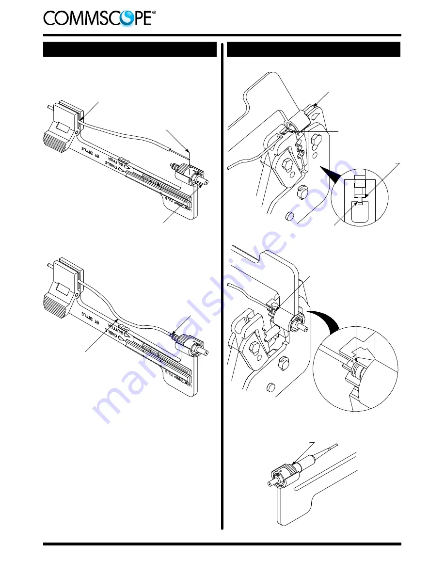
Figure 4: Crimping
Detail A
Detail B
Ferrule Facing
Outward
Buffer
(900--
m
m Bare Fiber)
or
Fiber
(250--
m
m Coated Fiber)
Held in Cable Clamp
Fiber Bottomed
in Plunger
Bend Formed to
Hold End of Fiber
in Place
Cleaved End of Fiber
Even with Front of
Arm of Cable Holder
Ferrule in Upper Cavity of
Front Die and Pointing in
Direction of Arrow
Plunger in Upper
Cavity of Rear Die
Detail A
Figure 5: Crimping
Tip in Channel
Disk Flat Against
Wall of Cavity
Bare Buffer Boot Over
Plunger and Against
Connector
Detail C
Detail B
Plunger in First Cavity of
Front Die with Ferrule
Pointing in Direction of Arrow
Shoulder of Plunger
Against Edge of
Groove in Die


