


408- 4457
7
of 16
Rev
J
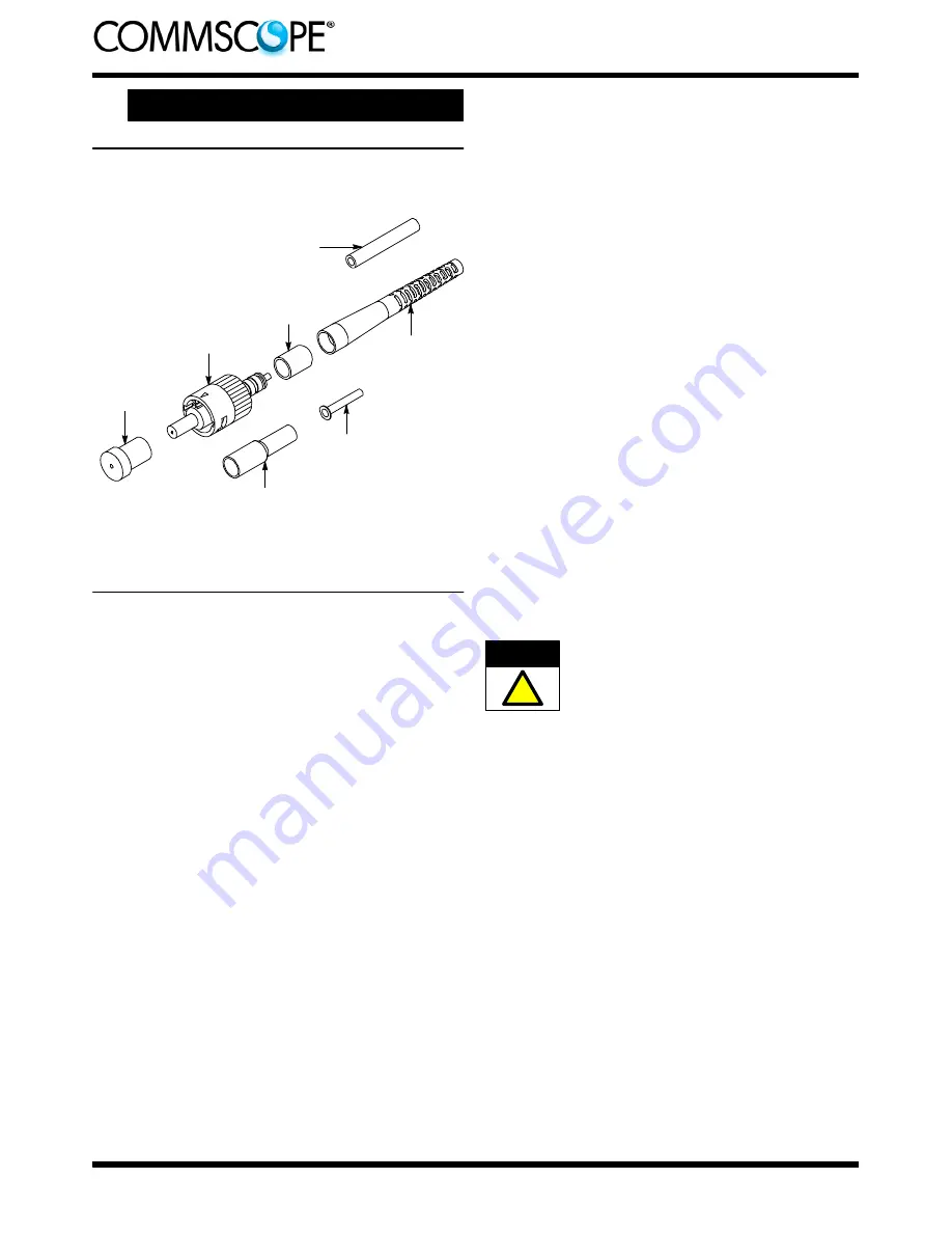
5.3.
2.0- to 3.0- mm Jacketed Cable
Kit Components Required
(Discard Other Components)
Connector
Assembly
Plunger
Protective
Cap
Strain
Relief
Crimp
Eyelet
Inner Eyelet
(Use Only With 2.5-- to
3.0--mm Jacketed Cable)
Black Tubing
(Use Only With 2.0-- to
2.4--mm Jacketed Cable)
Connector kit is shipped with these installed onto connector
assembly. Keep them in place until ready for assembly.
Ferrule
Protective
Cover
A. Preparing 2.0- to 3.0- mm Jacketed Cable
(Figures 6 and 7)
1. Slide the strain relief (small diameter end first)
over the cable. For cable with an outside diameter
from 2.0 to 2.4 mm, slide the black tubing over the
cable. See Figure 6, Detail A.
2. Remove the ferrule protective cover and the
plunger protective cap from the connector
assembly. Keep the cover; discard the cap.
3. Push the connector into the holder of the cable
holder with the ferrule protective cover facing
outward. See Figure 6, Detail B. Make sure that
the connector butts against the lip of the arm of the
cable holder. Slide the cable into the channel
marked “CABLE” on the cable holder. Make sure
that the tip of the jacket butts against the end of
the channel.
4. Mark the cable at each cross--slot of the
channel. See Figure 6, Detail B. Remove the cable
from the cable holder.
5. Using the strip tool, cut through the jacket at
each mark. See Figure 6, Detail C.
6. Remove the first jacket segment, and flare the
strength members away from the buffer. Using the
scissors, cut the strength members even with the
jacket. Then, remove the remaining jacket
segment. See Figure 6, Detail D.
7. If the cable outside diameter is 2.5 mm or larger,
slide the crimp eyelet onto the buffer and, using the
crimp eyelet, fold the strength members back over
the jacket. Continue sliding the crimp eyelet over
the jacket until the strength members appear at the
front of the crimp eyelet. See Figure 7, Detail A.
8. Slide the inner eyelet, non--flanged end first,
onto the buffer. Push the inner eyelet under the
strength members until the inner eyelet is flush
with the front of the crimp eyelet. See Figure 7,
Detail B.
9. Slide the buffer into the channel marked
“BUFFER” on the cable holder. Make sure that the
tip of the buffer butts against the end of the
channel. See Figure 7, Detail C.
10. Mark the buffer at each cross--slot of the
channel. See Figure 7, Detail C. Remove the buffer
from the cable holder.
11. Using the strip tool, strip the buffer to the first
mark. It is recommended holding the tool at an
angle to the buffer and stripping the fiber in three
sections. See Figure 7, Detail D. Clean the fiber
with an alcohol fiber wipe to remove fiber coating
residue.
Before using the fiber strip tool, make sure that
the “V” opening is clean; otherwise the fiber could
break. Only use isopropyl alcohol on the tool.
B. Cleaving
(Figure 8)
1. Open the fiber clamp of the fiber optic cleaver.
Press the button, and slide the carriage back
(toward the fiber clamp). Then move the fiber slide
back until it stops.
2. Place the stripped fiber into the slot so that the
end of the buffer is at the 8--mm marking. See
Figure 8, Detail A.
3. While applying pressure on the buffer, carefully
slide the fiber slide forward (toward the carriage)
until it stops. See Figure 8, Detail B.
4. Gently close the fiber clamp, and slide the
carriage forward. DO NOT touch the button while
sliding the carriage. See Figure 8, Detail C.
5. Open the fiber clamp, and move the fiber slide
back until it stops.
6. Remove the cleaved fiber, and properly dispose
of the scrap fiber.
CAUTION
!


