408- 4457
9
of 16
Rev
J
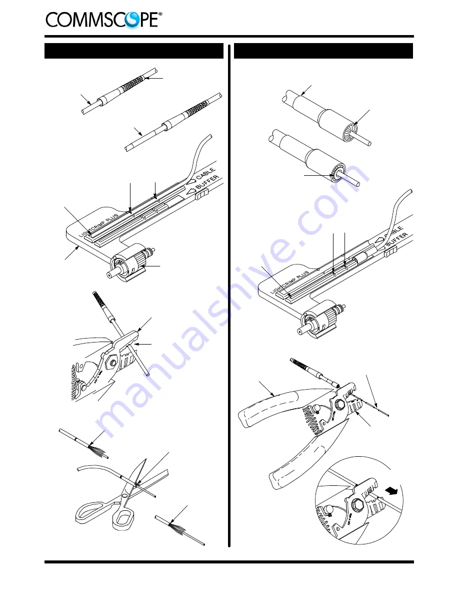
Detail A
First Jacket
Segment Removed
Detail D
Cut Strength Members
Even with Jacket
Remaining
Jacket Segment
Removed
Small Diameter
End of Strain
Relief
Cable
Detail C
Cut Through Jacket
Strip Tool
Figure 6: Preparing the Cable
For 2.0-- to 2.4--mm
Jacketed Cable
Black
Tubing
Tip of Jacket Against
End of Channel
Mark Jacket at
Cross--Slots
Detail B
Connector in Holder
with Ferrule Facing
Outward
Cable Holder
Assembly
Inner Eyelet Under
Strength Members
Strength Members
Folded Over Jacket
Detail A
Small Diameter End
of Crimp Eyelet
Detail B
Figure 7: Preparing the Cable
Detail D
Strip Buffer in
Sections to First Mark
Direction
of Strip
Hold Strip Tool at
45
_
Angle (Approx)
to Buffer
Strip Tool
Detail C
Tip of Buffer Against
End of Channel
Mark Buffer at
Cross--Slots