background image

ADCP-93-095 • Rev B • April 2018

Page 15

© 2018, CommScope, Inc.

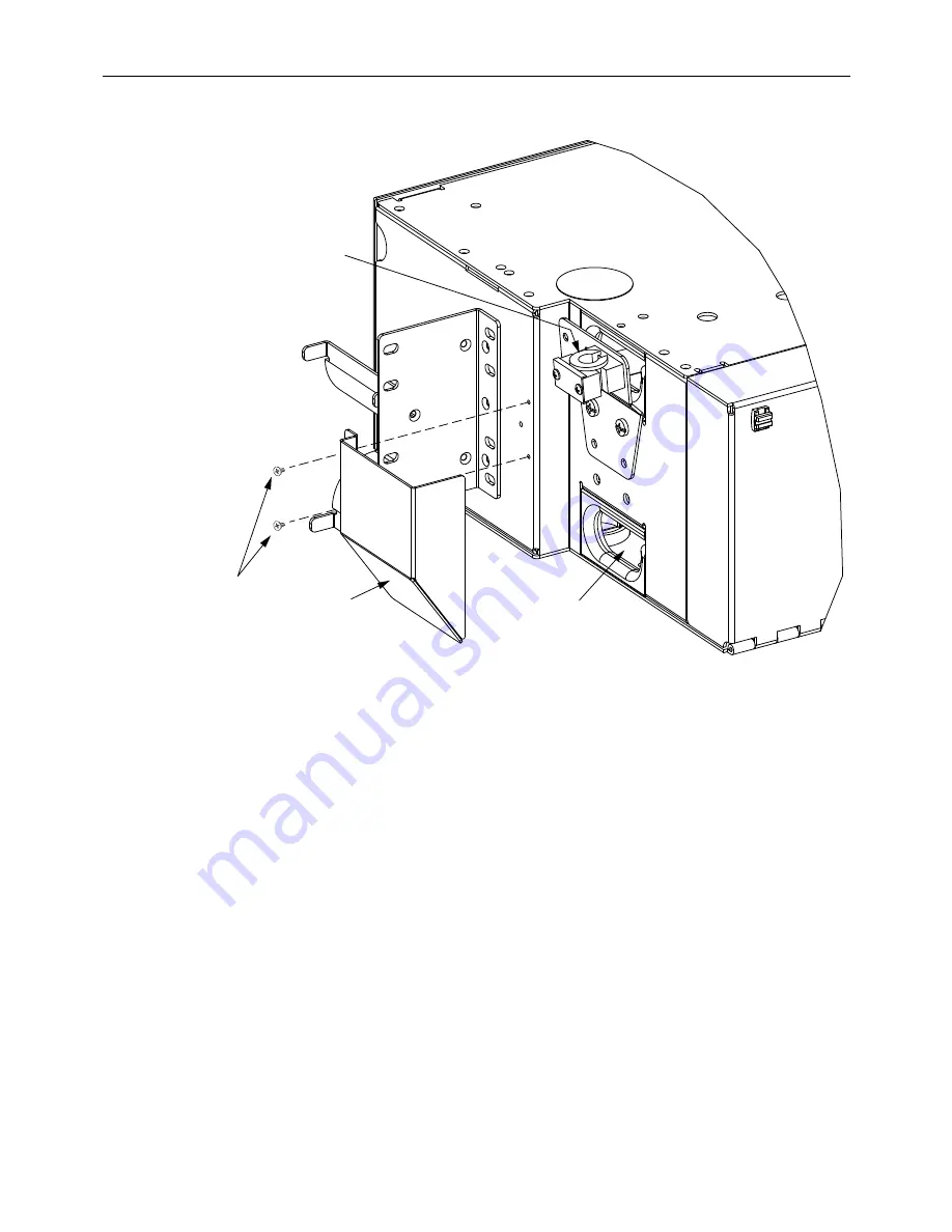
Figure 13. Cable Shield Components

(Shield Shown is Used With Overhead Cable)

5.5

Feeder Cable Routing

Separate procedures are provided in this section for different panel heights. For 7-inch and 9-
inch high panels, refer to 

Section 5.5.1 on Page 16

. For 1.75-inch and 3.5-inch high panels, refer 

to 

Section 5.5.2 on Page 17

CABLE

CLAMP

CABLE

SHIELD

CABLE

ENTRY HOLE

4-40X

SCREWS

(2)

17526-A

Summary of Contents for LSX

Page 1: ...odule 9 5 2 Grounding an Armored Cable 10 5 3 Breaking Out a Cable for Splicing 11 5 4 Installing a Cable Clamp 12 5 5 Feeder Cable Routing 15 5 5 1 Cable Routing for 7 Inch and 9 Inch High Panels 16 5 5 2 Cable Routing for 1 75 Inch High Panels 17 5 5 3 Cable Routing for 3 5 Inch High Panels 18 6 PATCH CORD ROUTING 19 6 1 Patch Cord Routing Within the LSX Module 19 6 2 Routing Patch Cords on the ...

Page 2: ...igtails and provides instructions for installation and operation Revision History quad cables and patch cord routing Trademark Information LGX and CommScope are trademarks Related Publications http www commscope com SupportCenter LGX Compatible LSX 288 Position Termination Splice Panel User Manual 93 103 LGX Compatible LSX Connector Module User Manual 93 089 Armored Plenum Compact Building Cable G...

Page 3: ...an OSP or IFC cable is routed through the panel to the splice area access door which serves as a splice deck On the splice area rear access door located on the rear of the panel the component fibers are spliced to the internal pigtails The factory terminated internal pigtails transition to the bulkhead located on the front of the panel Patch cords installed from the front side of the panel provide...

Page 4: ...f solid metal construction and painted white Nine 7 inch chassis or seven 9 inch chassis may be installed on an LGX frame Bulkhead holds the pass through adapters that provide the physical interface between the connector ends of internal pigtails and patch cords installed on the bulkhead Adapter Pack 6 8 12 or 24 pack depending on model mounts in the bulkhead providing one column of adapters conne...

Page 5: ...Splice Storage Spools provides service loop storage for cable fibers and pigtails Mass Fusion Splice Chip splices 24 fiber pigtail interfaces Splice Area Access Door folds down providing a horizontal splice deck Cable Ring routes and secures cable on entry into splice area Ribbon Fanout Bracket holds one stack of four ribbon fanout chips if ribbon rather than stranded pigtails are present Wing Nut...

Page 6: ...ows the 3 75 inch high panel Figure 4 Dimensions for 7 Inch and 9 Inch High Panel 14 84 IN 37 7 CM 16 84 IN 42 8 CM 18 15 46 1 CM 19 IN RACK MOUNT 48 3 CM 22 15 56 3 CM 23 IN RACK MOUNT 58 4 CM 7 53 IN 19 1 CM 15 0 IN 38 1 CM 5 0 IN 12 7 CM 7 0 IN 17 8 CM HEIGHT ON 72 OR 96 POSITION MODULES OR 9 0 22 9 CM HEIGHT ON 144 POSITION MODULES 1 0 IN 2 5 CM 1 0 IN 2 5 CM 2 0 IN 5 1 CM 17524 A 1 1 TOP VIEW...

Page 7: ...ure 6 Dimensions for 3 50 inch High Panel FRONT VIEW 16 84 IN 42 8 CM 19 33 49 1 CM 19 IN RACK MOUNT 48 26 CM TOP VIEW 23499 A 5 0 IN 12 7 CM 12 0 IN 30 5 CM 1 73 IN 4 4 CM FRONT VIEW 16 84 IN 42 8 CM 19 33 49 1 CM 19 IN RACK MOUNT 48 26 CM TOP VIEW 23500 A 5 0 IN 12 7 CM 12 0 IN 30 5 CM 5 23 IN 13 3 CM ...

Page 8: ...rminations 72 or 96 Dimensions HxWxD 7 0 x 17 0 x 12 0 inches 17 8 x 435 x 281 7 mm See Figure 4 Weight 25 lbs 11 34 kg 9 Inch High Panel Number of Terminations 144 Dimensions HxWxD 9 0 x 17 0 x 12 0 inches 22 9 x 435 x 281 7 mm See Figure 4 Weight 25 lbs 11 34 kg 1 75 Inch High Panel Number of Terminations 12 or 24 Dimensions HxWxD 1 73 x 17 0 x 12 0 inches 4 4 x 43 1 x 30 5 cm See Figure 5 Weigh...

Page 9: ...equires shipment at a future date 5 INSTALLATION The main steps in installing an LSX panel are Mounting the panel on the frame Breaking out the cable to be spliced within the panel Installing the cable on the outside of the panel and Routing the cable within the panel from the cable clamp to the splice deck For instructions refer to the following subsections 5 1 Installing the Combination Module I...

Page 10: ...re the mounting brackets to the rack front flange using six 12 24 mounting screws 5 2 Grounding an Armored Cable When installing an armored cable a procedure is required before breaking out the cable to sever and ground the armor A CommScope kit is available for grounding the armor catalog GND STPKIT For details refer to the instructions shipped with the kit ADCP 90 382 Note If jumper retainers ar...

Page 11: ...stalling blocking and grounding kits if required refer to the instructions contained in the kits Note Kits for stranded cable breakouts are available from CommScope Refer to catalog 804 or contact CommScope Customer Assistance For contact information see Section 8 Chassis Height Dimension A Dimension B 1 75 in 12 0 in 0 0 1 0 in 30 5 cm 0 0 2 5 cm 38 6 in 0 0 6 0 in 96 5 cm 0 0 15 0 cm 3 5 in 12 0...

Page 12: ...s in the standoff mounting holes in the cable clamp bracket Note The figures show the cable clamp bracket positioned for cable routing from above the panel For cable routing from below the panel turn the cable clamp bracket upside down compared to how it is shown in the figure and use the mounting holes designated in the figure as for under floor cable entry Note There are four standoff mounting h...

Page 13: ...was installed stack the cable clamp components on the standoffs as shown in Figure 10 and Figure 11 with the cable secured within the rubber grommet Position the cable so that the breakout point shown in Figure 8 and Figure 9 occurs just beyond the rubber grommet 6 Secure the cable clamp components to the standoffs using standoff screws as shown in Figure 10 and Figure 11 7 If desired install a ca...

Page 14: ...BLE CLAMP BRACKET OVERHEAD CABLE POSITION YOKE 2 CABLE CLAMP COVER 12 24X SCREW 2 STANDOFF 2 STANDOFF MOUNTING HOLE 4 STANDOFF SCREW 2 17534 A RUBBER GROMMET CLAMP MOUNT PLATE CABLE CLAMP BRACKET MOUNTING HOLES 2 FOR UNDER FLOOR CABLE ENTRY ALTERNATIVE CABLE CLAMP BRACKET MOUNTING HOLES 2 FOR UNDER FLOOR CABLE ENTRY CABLE CLAMP BRACKET MOUNTING HOLES 2 FOR OVERHEAD CABLE ENTRY ALTERNATIVE CABLE CL...

Page 15: ...erhead Cable 5 5 Feeder Cable Routing Separate procedures are provided in this section for different panel heights For 7 inch and 9 inch high panels refer to Section 5 5 1 on Page 16 For 1 75 inch and 3 5 inch high panels refer to Section 5 5 2 on Page 17 CABLE CLAMP CABLE SHIELD CABLE ENTRY HOLE 4 40X SCREWS 2 17526 A ...

Page 16: ...tical loop by looping the cable twice through the rear set of curleyloks following the same route as the internal pigtails in the front set of curleyloks 2 Route the cable to the splice area access door 3 Tie down the cable at the point where the exposed fibers emerge from the breakout per the breakout dimensions provided in subsection 5 3 Figure 14 Cable Routing 7 and 9 Inch High Panel CABLE CLAM...

Page 17: ...from the entry hole horizontally across the rear storage area and into the extended drawer 2 Loop the cable around twice on the drawer and tie it down with lacing in the locations shown 3 Route the cable to the splice tray as shown 4 Tie down the cable at the point where the exposed fibers emerge from the breakout per the breakout dimensions provided insubsection 5 3 Figure 15 Cable Routing 1 75 I...

Page 18: ...from the entry hole horizontally across the rear storage area and into the extended drawer 2 Loop the cable around twice on the drawer and tie it down with lacing in the locations shown 3 Route the cable to the splice tray as shown 4 Tie down the cable at the point where the exposed fibers emerge from the breakout per the breakout dimensions provided insubsection 5 3 Figure 16 Cable Routing 3 5 In...

Page 19: ...LSX Module Patch Cord Guides and Radius Limiters Danger Infrared radiation is invisible and can seriously damage the retina of the eye Do not look into the ends of any optical fiber Do not look directly into the optical adapters of the adapter packs Exposure to invisible laser radiation may result An optical power meter should be used to verify active fibers A protective cap or hood MUST be immedi...

Page 20: ...s can be used when both ends are terminated in the top half of the bay Use the following procedure to route patch cords on a stand alone bay 1 Loop the patch cord across the upper raceway 2 Route the right side of the patch cord down through the right vertical trough to the LSX panel where the right side of the patch cord will be terminated 3 Route the left side of the patch cord down through the ...

Page 21: ...Scope Inc Figure 18 Routing Patch Cords on a Stand Alone Bay BAY 3 3 2 2 BAY SAME SIDE TERMINATIONS OPPOSITE SIDE TERMINATIONS 1 1 17536 A JUMPER RETAINERS VERTICAL TROUGH VERTICAL TROUGH UPPER RACEWAY VERTICAL TROUGH VERTICAL TROUGH UPPER RACEWAY ...

Page 22: ...erminated in the top left of the frame To route patch cords between adjacent bays shown in Figure 19 use the following procedure Figure 19 Routing Patch Cords Between Adjacent Bays 1 Terminate one end of the patch cord on the originating LSX panel and bay then route the patch cord left or right to the nearest vertical trough BAY BAY 17537 A 1 1 2 2 3 3 JUMPER RETAINERS JUMPER SUPPORT BRACKET VERTI...

Page 23: ...h you must take into account the number of bays to be traversed and which raceways will be used to route the patch cord To select a patch cord based on these factors refer to Table 2 N A Not applicable Table 2 Patch Cord Selection Table BOTTOM HALF ORIGIN BOTTOM HALF DESTINATION LOWER TO LOWER RACEWAY NUMBER OF BAYS 3 4 5 6 7 8 9 10 11 12 13 14 15 16 17 18 19 20 21 N A JUMPER LENGTH 7 6 m 25 ft 9 ...

Page 24: ...rd left or right to the nearest vertical trough 2 Route the end of the patch cord terminated in step 1 down the left or right vertical trough to the lower raceway Figure 20 Routing Patch Cords Starting in the Lower Raceway Bottom to Bottom BAY BAY BAY 17538 A ORIGINATING TERMINATION LOCATIONS DESTINATION TERMINATION LOCATIONS JUMPER RETAINERS JUMPER SUPPORT BRACKET VERTICAL TROUGH VERTICAL TROUGH ...

Page 25: ...ds in the lower raceway between the origin and destination bays Adjust the slack loops in the vertical troughs to prevent buildup within the raceway Figure 21 Routing Patch Cords Starting in the Lower Raceway Bottom to Top Note Use the lower trough as the main raceway since it tends to be less congested Route the patch cord through the upper raceway for one bay length only BAY BAY BAY 17540 A ORIG...

Page 26: ... the left or right vertical trough to the upper raceway 3 At the destination panel and bay terminate the opposite end of the patch cord and then route the patch cord left or right to the nearest vertical trough 4 Route the patch cord terminated in step 3 up the left or right vertical trough as shown in Figure 22 and Figure 23 Figure 22 Routing Patch Cords in the Upper Raceway Top to Top BAY BAY BA...

Page 27: ...s in the vertical troughs to prevent buildup within the raceway Figure 23 Routing Patch Cords in the Upper Raceway Top to Bottom BAY BAY BAY 17541 A ORIGINATING TERMINATION LOCATIONS DESTINATION TERMINATION LOCATIONS JUMPER RETAINERS JUMPER SUPPORT BRACKETS VERTICAL TROUGH VERTICAL TROUGH VERTICAL TROUGHS VERTICAL TROUGHS VERTICAL TROUGHS UPPER RACEWAYS 1 2 5 4 3 ...

Page 28: ...t cover of the chassis may be removed to provide easier access for cable routing To remove a cover lift it straight out of the hinges To replace a cover position the hinge edge of the cover on the hinges and press inward to push the edge into the hinges 7 2 Patching and Testing Danger Infrared radiation is invisible and can seriously damage the retina of the eye Do not look into the ends of any op...

Page 29: ...ical circuits are done on the front of the LSX panel using patch cords Whenever patch cords are installed route them down and to the side as with cross connect patch cords Refer to Figure 25 below see also Figure 17 on page 19 Figure 25 Correct Routing of Patch Cords TOP VIEW 17519 A ...

Page 30: ...OMER INFORMATION AND ASSISTANCE To find out more about CommScope products visit us on the web at www commscope com For technical assistance customer service or to report any missing damaged parts visit us at http www commscope com SupportCenter ...

Reviews: