ADCP-93-095 • Rev B • April 2018
Page 25
© 2018, CommScope, Inc.
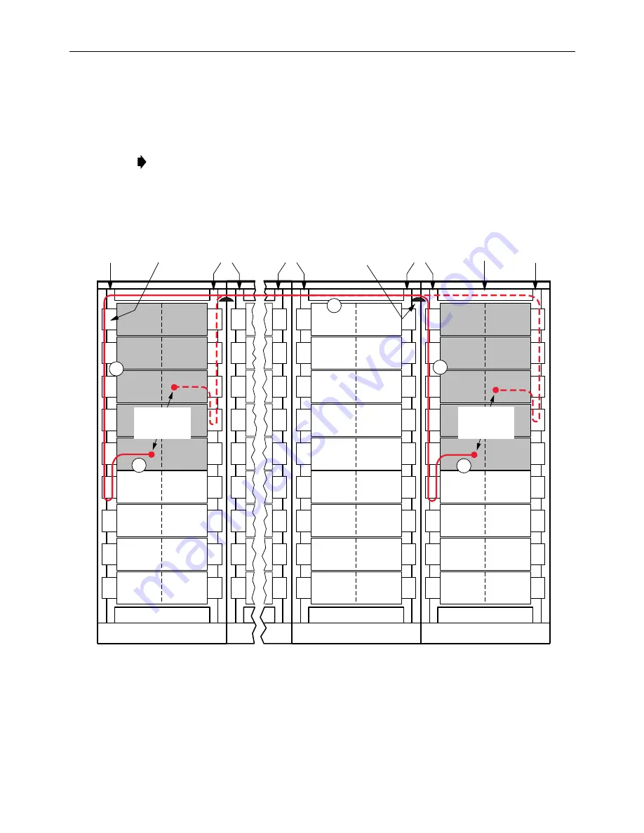
3. At the destination panel and bay, terminate the opposite end of the patch cord, then route
the patch cord left or right to the nearest vertical trough.
4. Route the end of the patch cord terminated in step 3 up the left or right vertical trough and
over the upper raceway across the top of one bay as shown in
5. Insert the patch cords in the lower raceway between the origin and destination bays.
Adjust the slack loops in the vertical troughs to prevent buildup within the raceway.
Figure 21. Routing Patch Cords Starting in the Lower Raceway (Bottom to Top)
Note:
Use the lower trough as the main raceway since it tends to be less congested. Route
the patch cord through the upper raceway for one bay length only.
BAY
BAY
BAY
17540-A
ORIGINATING
TERMINATION
LOCATIONS
DESTINATION
TERMINATION
LOCATIONS
JUMPER
RETAINERS
JUMPER
SUPPORT
BRACKETS
VERTICAL
TROUGH
VERTICAL
TROUGH
VERTICAL
TROUGHS
VERTICAL
TROUGHS
VERTICAL
TROUGHS
UPPER
RACEWAYS
1
2
5
4
3


