background image

860481019 
Instruction Sheet 


www.commscope.com 


Page 2 of 7 

Parts List 

Verify parts against the parts list below: 

Quantity 

Description 

M2400 Panel 

M2400A Panel 

PS 

GS 

PS 

GS 

― 

― 

M2400 panel assembly 

― 

― 

M2400A panel assembly 

― 

― 

Panel end caps 

25 

― 

25 

― 

MPS/UNJ outlet caps 

― 

25 

― 

25 

MGS outlet caps 

12-24 x 1/2” mounting screws 

Label sheet 

Instruction sheet 

Separately Orderable Items 

A separately orderable rear cable management bar is available for use with the M2400/M2400A panel and a 
separately orderable removal tool kit is required for use with the panel. 

Material ID 

Description 

760104737 

Rack mountable rear cable management bar 

760122713 

Outlet removal tool kit (5 pack) 

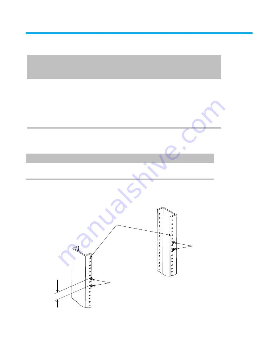
Step 1A – M2400 Flat Panel Installation (Skip to Step 1B for Installation of M2400A 
Angled Panel) 

Install Mounting Screws 

12-24 x 1/2” screw

12-24 x 1/2” screw

1U panel
spacing

19-inch equipment rack


1.  Partially install four 12-24 x 1/2” screws in equipment uprights in a 1U panel spacing as shown. 

Summary of Contents for M2400 Series

Page 1: ...n is listed below Material ID Part No Description 760118323 M2400 1U GS M2400 GS panel GigaSPEED 760118315 M2400 1U PS M2400 PS panel PowerSUM UNJ 760118349 M2400A 1U GS M2400A GS panel GigaSPEED 760118331 M2400A 1U PS M2400A PS panel PowerSUM UNJ M2400 Patch Panel M2400A Patch Panel How to Contact Us To find out more about CommScope products visit us on the web at http www commscope com For techn...

Page 2: ... Items A separately orderable rear cable management bar is available for use with the M2400 M2400A panel and a separately orderable removal tool kit is required for use with the panel Material ID Description 760104737 Rack mountable rear cable management bar 760122713 Outlet removal tool kit 5 pack Step 1A M2400 Flat Panel Installation Skip to Step 1B for Installation of M2400A Angled Panel Instal...

Page 3: ...t to engage screws 12 24 x 1 2 screw 1 Position panel against rack rails offset to the left of the partially installed screws 2 Align slots in panel with screws and slide panel to right to engage screws Secure Panel to Rack holes in panel 1 Use a screwdriver to access screws through holes in panel Tighten screws to secure panel to rack ...

Page 4: ... Snap end caps into place on panel as shown Step 1B M2400A Angled Panel Installation Install Panel on Rack 12 24 x screws 19 inch equipment rack M2400A panel 12 24 x screws 1 Use four supplied 12 24 x screws to secure panel to rack 2 Connect cables to outlets per instructions provided with the individual outlets ...

Page 5: ...ps on Outlets and Populate Panel 1 Terminate cables to outlets per the instructions provided with the individual outlets Note Use a D914 impact tool on HI setting with M110 cutting blade and hand puck or the JackRapid termination tool to punch down conductors Trimming conductors with side cutters or fine edge cutters is not allowed due to the tight spacing of the outlets 2 After termination of out...

Page 6: ...bels for port designation Icons 1 Apply labels and icons to front of panel as shown for port designation Step 5 Using Module Removal Tool Part of Removal Tool Kit 760122713 To Remove End Cap Insert tool into slot Slot End cap 1 Insert provided tool into slot as shown 2 Use tool to pry end cap loose from panel ...

Page 7: ...tool 1 Position tool as shown and insert into front of outlet to depress locking tabs 2 Remove outlet from rear of panel To Remove Modular Cap Insert end of tool into slot under cap Slot Pivot tool forward to disengage cap 1 Insert tool into slot as shown and pivot forward to disengage modular cap for removal from outlet ...

Reviews: