www.commscope.com
860481019
Issue 4, November 2012
Page 5 of 7
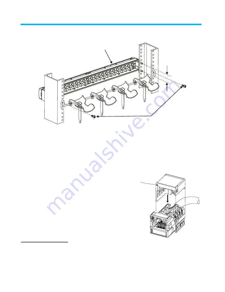
Step 2 ― Attach Separately Orderable Cable Management Bar
1U panel spacing
12-24 x 1/2” screws
M2400 panel shown
1. Attach cable management bar to rear of equipment rack using the four provided 12-24 x 1/2” screws as
shown. Bar should be level with lower row of outlets.
2. Assemble cable management bar components per instructions provided with the bar.
Step 3 – Terminate Outlets, Install Modular Caps on Outlets, and Populate Panel
1. Terminate cables to outlets per the instructions
provided with the individual outlets.
Note:
Use a D914 impact tool (on HI setting)
with M110 cutting blade and hand puck or the
JackRapid* termination tool to punch down
conductors.
Trimming conductors with side-cutters
or fine edge cutters is not allowed due to the tight
spacing of the outlets.
2. After termination of outlets, snap the provided
modular caps onto the outlets.
3. Populate the panel with outlets, then using the
instructions provided with the cable bar, route and
secure cables to bar using the provided hook-and-
loop straps.
*Trademark of Fluke Networks.
Modular cap


