TECP-90-708 • Issue 5 • April 2017
Page 17
© 2017, CommScope, Inc.
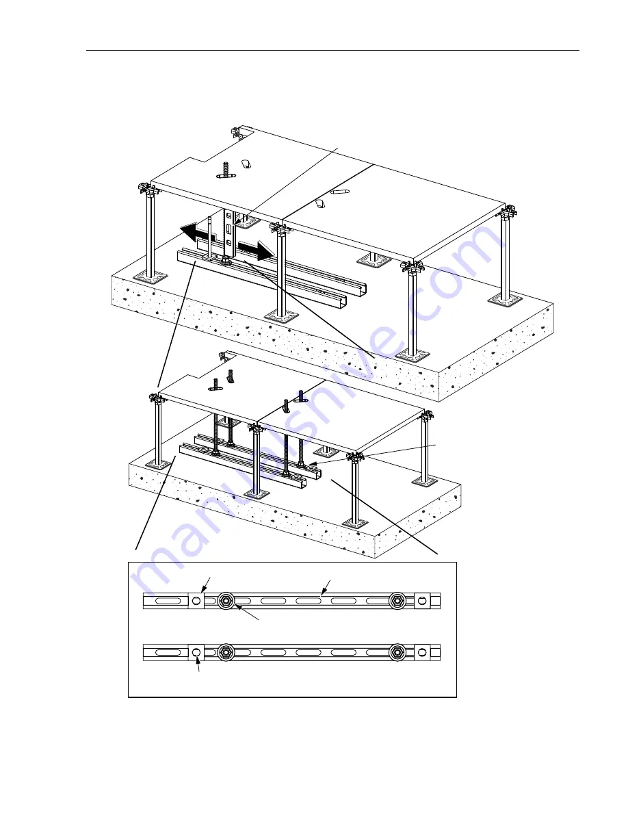
12. Plumb the threaded rod assembly and mark anchor plate location on concrete. Install three
remaining threaded rod assemblies in the same manner. See
Figure 13
.
Figure 13. Installing Threaded Rod Assemblies
PLUMB THREADED ROD
FROM
S
IDE TO
S
IDE
25055-A
ANCHOR PLATE
X
X
X
X
UNI
S
TRUT
THREADED ROD A
SS
EMBLY
AND
S
PRING NUT
MARK CONCRETE
(FOUR PLACE
S
)
TOP VIEW
IN
S
TALL REMAINING
THREADED ROD
A
SS
EMBLIE
S


