TECP-90-708 • Issue 5 • April 2017
Page 30
© 2017, CommScope, Inc.
a. Install the Raised Floor Cable Clamp Bracket Kit (separately ordered). For
instructions on how to install the kit, refer to
Section 5 on Page 35
.
b. If the cables from under the floor will be routed into a splice chassis, install a spool
bracket assembly. For instructions, refer to
Section on Page 46
.
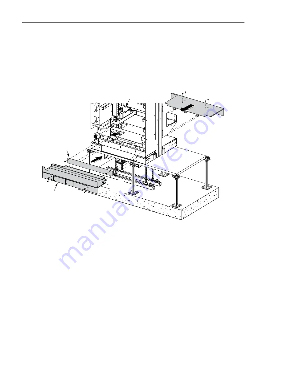
26. Re-install front and rear trough as shown in
Figure 26
.
27. Ground the frame. Refer to
Section 9 on Page 49
.
Figure 26. Re-installing Troughs
4
INSTALLING A FIBER OPTIC STORAGE PANEL (FOTSP)
A Fiber Optic Storage Panel (FOTSP), installed onto the left side of the NG4access frame as
looking from the front, provides storage space on the rear for Fiber Optic Terminal Equipment
patch cords. The FOTSP is 12 inches wide. For a view of the frame and FOTSP footprints, refer
to
Section 2 on Page 6
. Use the following procedure to install a FOTSP.
1. If the front trough covers, front guard box, and the rear guard box, are present on the
frame, remove them.
Figure 26
above shows the same components, but being installed.
2. If cables will enter the FOTSP from under the floor, saw out a cable entry hole, referring to
Figure 2 on Page 6
for hole location and dimensions.
3. Unpack the FOTSP and set it up next to the frame, with the cross-frame troughs on the rear
side corresponding to the location of the cross-frame troughs on the frame.
FRONT
VIEW
LOWER
TROUGH
BACK
LOWER
TROUGH
BA
S
E
GUARD BOX
COVER
25069-A
REAR
GUARD BOX


