TECP-90-708 • Issue 5 • April 2017
Page 40
© 2017, CommScope, Inc.
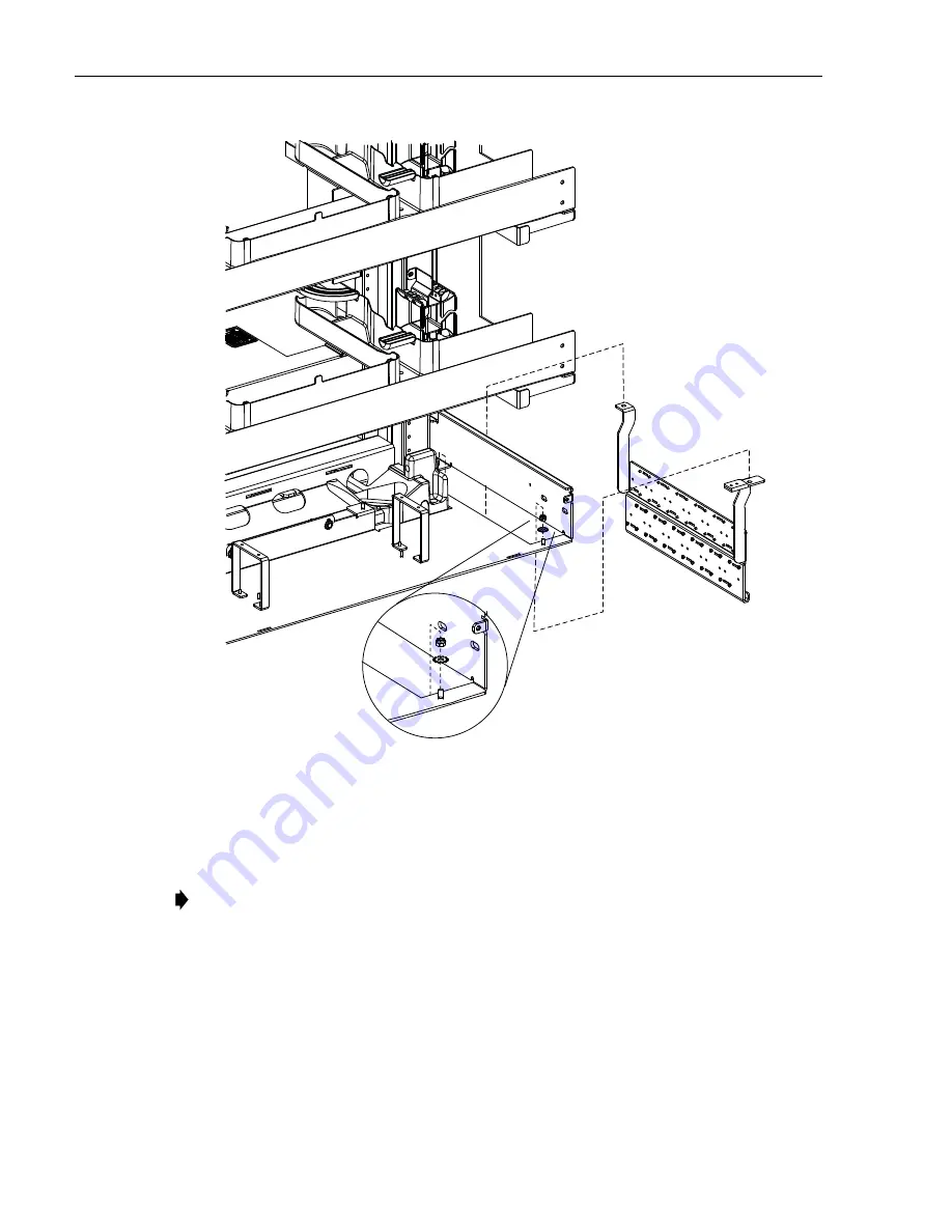
Figure 39. Installing Bracket in Frame
6. Route the cables to be installed through the entry hole, taking care to position each cable
on the correct side of the raised floor cable breakout per the cable clamp locations shown
in
Figure 33 on Page 36
.
7. Prepare each cable as follows, referring to
Figure 40
:
a. Pull the cable up through the hole.
b. If the cable being installed is an NG4access cable terminated with one or more cabled
module(s), obtain the appropriate DIM ‘A’ length from
Table 5
based on where the
cable clamp will be installed on the bracket, measure out this length from the factory
breakout on the cable, and mark the cable at this location as shown in
Figure 40
. This
is where the cable clamp should be placed on the cable.
Note: The Row locations shown in this same figure (
Figure 33 on Page 36
) will also be
used to figure out the DIM ‘A” values when breaking out the cables in the next step.
PO
S
ITION BRACKET ON
THREADED
S
TUD.
IN
S
TALL #10 WA
S
HER
AND #10 NUT
(TWO PLACE
S
).
TIGHTEN TO 16 INCH-LB
S
.
(1.8 NEWTON METER
S
)
25171-A


