TECP-90-708 • Issue 5 • April 2017
Page 45
© 2017, CommScope, Inc.
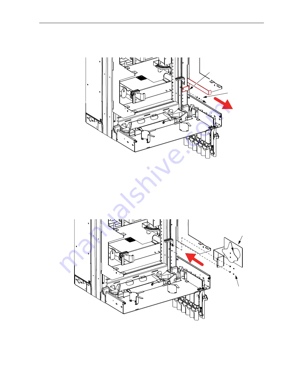
2. Remove and discard #12 washer and screw securing vertical cable guide next to the
bottom chassis, as shown in
Figure 47
. Discard screw, washer, and cable guide.
Figure 47. Removing Vertical Cable Guide
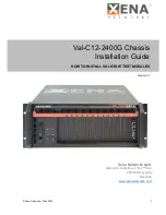
3. Locate the spool bracket assembly that came with the Standard Cable Bracket Kit, and
install the bracket in the location from which the vertical cable guide was just removed as
shown in
Figure 48
. Install the two screws and washers provided using the hole from
which the standard bracket screw was just removed and the hole above it. Torque to 18
inch-pounds (2.03 Newton meters).
Figure 48. Installing Spool Bracket
25170-A
REAR VIEW
OF FRAME
NOTE:
FOR CLARITY
S
OME
S
HEET METAL
REMOVED FROM FRAME
REMOVE
VERTICAL CABLE
GUIDE
REMOVE
AND
DI
S
CARD
S
CREW
AND
WA
S
HER
2514
3
-A
REAR VIEW
OF FRAME
NOTE:
FOR CLARITY
S
OME
S
HEET METAL
REMOVED FROM FRAME
IN
S
TALL TWO EACH
MOUNTING
S
CREW
S
AND LOCK WA
S
HER
S
(#12 PANHEAD).
TIGTHEN TO 18 INCH-LB
S
.
(2.0
3
NEWTON METER
S
)
S
POOL
BRACKET
A
SS
EMBLY


