TECP-90-708 • Issue 5 • April 2017
Page 46
© 2017, CommScope, Inc.
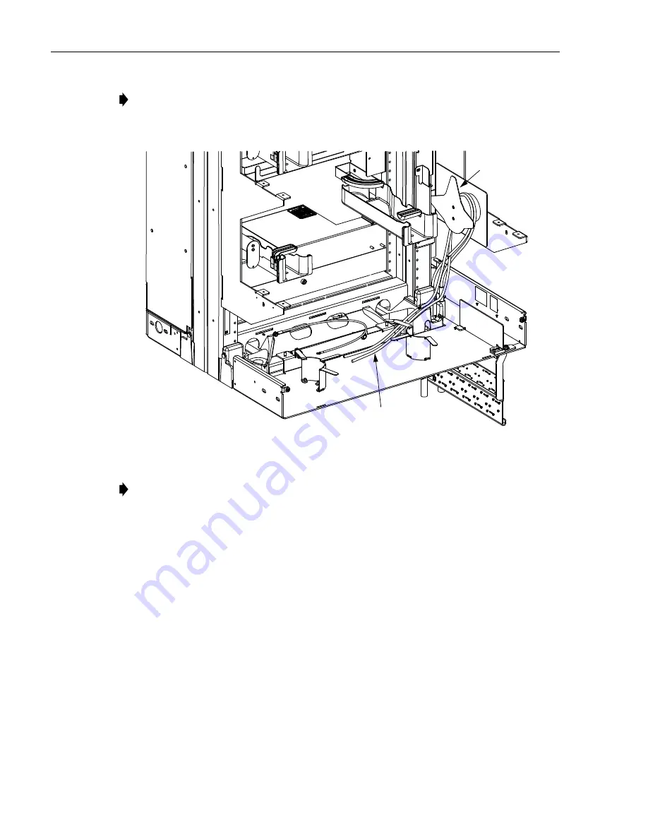
Figure 49. Routing Cables On Spool Bracket
4. Slide the splice chassis back into the frame.
5. Re-install the front plate removed in
Step 3 on Page 38
.
7
INSTALLING AUXILIARY CABLE SPOOLS (FOR FRAMES WITHOUT SPLICE CHASSIS)
If the frame on which the bracket was just installed does not have a splice chassis (cables will be
routed to the universal chassis), auxiliary cable spool brackets (separately ordered) must also be
installed. The purpose of these spools is to provide a means for looping the cables over before
they are routed into the universal chassis. One kit is required for each universal chassis on the
right rear side only. Before the kit can be installed, the vertical cable guide in that location must
be removed.
Note: When routing a cable from the cable clamp bracket to the splice chassis, bring the
cable up in front of the spool and loop the cable back and over the spool then down into
the area below the splice chassis as shown in
Figure 49
.
Note: For instructions on routing the cables into the splice chassis and splice chips, refer
to NG4access ODF Platform Splice Chassis and Splice Tray User Manual (TECP-90-
704). This procedure only covers the spool bracket.
25144-A
CABLE ROUTED INTO AREA
BELOW
S
PLICE CHA
SS
I
S
BACK
PLATE
REAR VIEW
(
S
PLICE
CHA
SS
I
S
REMOVED)


