TECP-90-708 • Issue 5 • April 2017
Page 48
© 2017, CommScope, Inc.
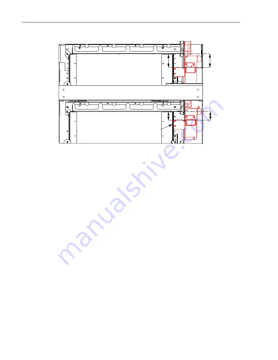
Figure 52. Rear View of Bracket Locations (Top Two Chassis)
8
GROUNDING THE FRAME
Standard grounding is accomplished by connecting a compression lug to a grounding point on
the top member of the frame, as shown in
Figure 53
.
Any 2-hole location with the correct hole spacing may be used. Use a 2-hole #10 compression
lug with 3/4 inch hole (1.905 cm) spacing.
Scrape the paint to expose bare metal and apply deoxidant in the grounding location. For a
grounding wire, use only 6 AWG or thicker copper wire.
25242-A
MOUNTING
HOLE
S
2.78 IN.
(7.06 CM)
1.81 IN.
(4.60 CM)
TOP CHA
SS
I
S
ON FRAME
ALL OTHER
CHA
SS
I
S
BOTTOM
HOLE
MOUNTING
UPPER
HOLE
MOUNTING


