ADCP-96-806 • Issue 4 • July 2016
Page 10
© 2016
CommScope
. All Rights Reserved.
Route the fibers from the distribution/subscriber cable(s) to the splice trays that have individual
yellow
jacketed
pigtail fibers attached to them. The yellow jacketed fibers are routed to the
adapter/parking panels on the interconnect side of the center swing panel.
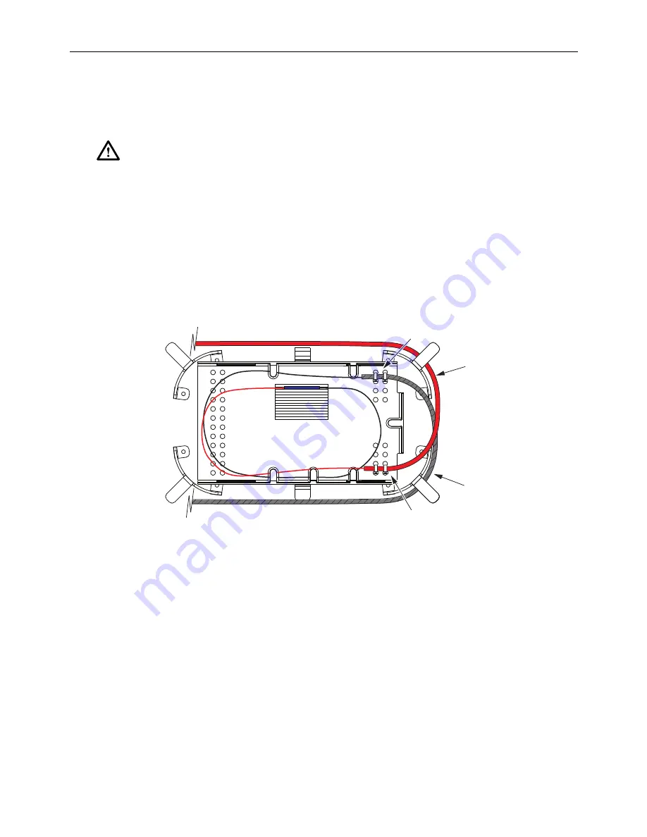
Follow local practices and procedures for splicing. Splice holders for ribbon and fusion splicing
are provided separately. Use cable ties to secure fibers to the splice tray as shown in
After splicing is complete manage the fiber in loops around the splice trays and secure the trays
in place with the O-rings. Use caution when closing the cabinet to avoid pinching any fibers or
tubes, especially along the hinged area.
Figure 8. Splice Tray Typical Installation
6
INTERCONNECTIONS
The IFDT may be ordered with or without parking. When the parking option is ordered, the
distribution/subscriber connectors may be temporarily “parked” until service is required.
Cabinets that do not include parking lots have twice as much termination capacity.
For cabinets that not equipped with pre-installed distribution/subscriber pigtails, four entry
ports are provided (two at the top and bottom) for routing jumpers into the cabinet front section.
Cable tie mounting blocks are provided separately for managing jumpers within the cabinet.
Punch a hole through the soft rubber material covering the selected jumper entry port and then
route the jumper into the cabinet.
Warning:
Invisible infrared radiation can seriously damage the retina of your eye. Do not look
into the launching (output) end of an active fiber. A clean, protective cap or hood MUST be
immediately placed over any radiating bulkhead receptacle or optical connector to avoid
exposure to potentially dangerous amounts of radiation. This practice also helps to prevent
contamination of connectors and adapters.
FACTORY-IN
S
TALLED
PIGTAIL A
SS
EMBLY
CABLE FIBER
S
CABLE
TIE POINT
PIGTAIL
TIE POINT
23120-A


