


ADCP-96-806 • Issue 4 • July 2016
Page 7
© 2016
CommScope
. All Rights Reserved.
Both feeder/provider and distribution/subscriber cables may be installed using this procedure,
Determine the entry point that will be used for routing the cable into the cabinet and then follow
the installation procedure that is appropriate for the cable.
4.1
Securing Cables to the Cabinet Using a Compression Fitting
Multi-fiber jacketed cables with a diameter ranging from 0.5 to 0.71 inches may be secured at
the cabinet entry point using one of the compression fittings provided. Use the following
procedure to secure a cable to the cabinet using a compression fitting:
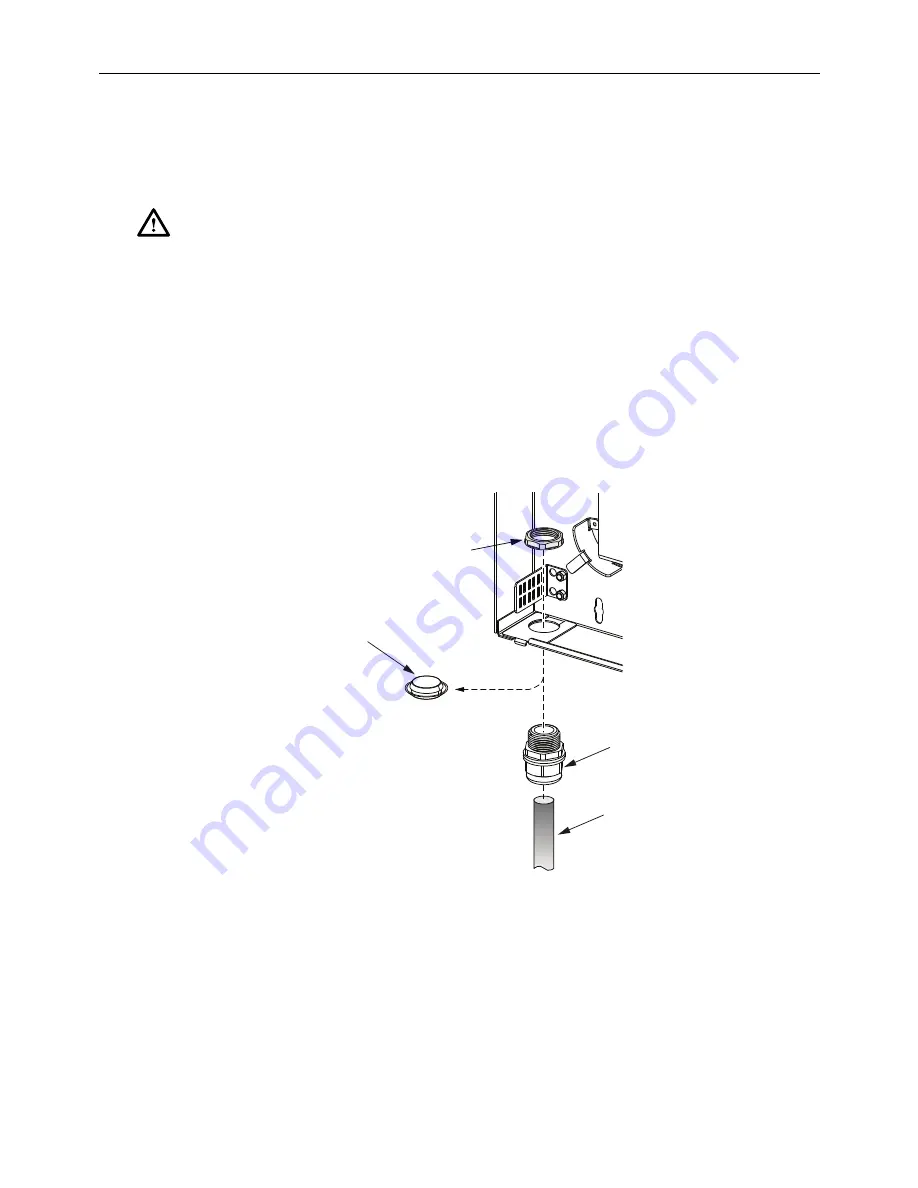
1. Remove the plastic dust cap from the selected cable entry port in the cabinet.
2. Locate one of the compression fittings that are shipped with the cabinet
3. Install the compression fitting in the cabinet as shown in
Figure 5. Compression Fitting Installation
4. Feed approximately 9 feet of the cable through the compression fitting and into the
enclosure.
5. Strip away approximately 8 feet of the cable jacket to expose the buffer tubes, 900 micron
fiber, or ribbon. Clean if necessary.
6. Adjust cable so approximately 2 inches of the cable sheath extends into the cabinet and
then tighten the compression fitting nut to secure the cable to the cabinet.
Caution:
Improper handling can damage fiber optic cables. Do not bend fiber optic cable more
sharply than the minimum recommended bend radius specified by the cable manufacturer. Do not
apply more pulling force to the cable than specified. Do not compress the fiber or allow it to kink.
NUT
COMPRE
SS
ION
FITTING
PLA
S
TIC
DU
S
T CAP
(REMOVE)
CABLE
(0.5 TO 0.71 IN)
23118-A


