background image

ADCP-96-159 • Issue 4 • March 2017 • Preface

Page 3

© 2017, CommScope, Inc. All Rights Reserved.

ABOUT THIS MANUAL

This publication provides user information for the OmniReach DLX Mini Multiport Service
Terminal (MST) which includes the models designated MST-04D, MST-06D, MST-08D and
MST-12D. The topics covered include a basic description of the MST; installation and mounting
guidelines; and procedures for using and maintaining the hardened connectors and adapters.

RELATED PUBLICATIONS

Listed below are related manuals and their publication numbers. Copies of these publications can
be ordered by contacting the CommScoope Technical Assistance Center (refer to

 Section 7 on

Page 20

).

CommScope OmniReach® DLX™ Connector and Adapter Cleaning Instructions

96-163

Universal Mounting Bracket Strand-Mount Installation Instructions

96-124

ADMONISHMENTS

Important safety admonishments are used throughout this manual to warn of possible hazards to
persons or equipment. An admonishment identifies a possible hazard and then explains what
may happen if the hazard is not avoided. The admonishments — in the form of Dangers,
Warnings, and Cautions — must be followed at all times. These warnings are flagged by use of
the triangular alert icon (seen below) and are listed in descending order of severity of injury or
damage and likelihood of occurrence.

GENERAL SAFETY PRECAUTIONS

Title

ADCP Number

Danger: Danger is used to indicate the presence of a hazard that will cause severe personal
injury, death, or substantial property damage if the hazard is not avoided.

Warning: Warning is used to indicate the presence of a hazard that can cause severe personal
injury, death, or substantial property damage if the hazard is not avoided.

Caution:  Caution is used to indicate the presence of a hazard that will or can cause minor
personal injury or property damage if the hazard is not avoided.

Warning:  Wet conditions increase the potential for receiving an electrical shock when
installing or using electrically-powered equipment. To prevent electrical shock, never install or
use electrical equipment in a wet location or during a lightning storm. 

Caution: Fiber optic cables may be damaged if bent or curved to a radius that is less than the
recommended minimum bend radius. Always observe the recommended bend radius limit when
installing fiber optic cables and patch cords. 

Summary of Contents for OmniReach RLX

Page 1: ...4 PORT 6 PORT 8 PORT 12 PORT 23544 B ADCP 96 159 Issue 4 March 2017 User Manual OmniReach DLX Mini Multi Port Service Terminal ADCP 96 159 Rev B www commscope com ...

Page 2: ...ing from loss of data loss of use or loss of profits and CommScope further disclaims any and all liability for indirect incidental special consequential or other similar damages This disclaimer of liability applies to all products publications and services during and after the warranty period This publication may be verified at any time by contacting CommScope using the link provided below PRODUCT...

Page 3: ...aterials Required for Installation 5 2 3 Unpacking and Inspection 6 3 GENERAL INSTALLATION INFORMATION 6 3 1 Cable Handling Recommendations 6 3 2 Fiber and Port Configuration 7 4 MOUNTING THE MULTIPORT SERVICE TERMINAL 8 4 1 MST Mounting Options 8 4 2 Installing the UMB and MST 10 5 USING COMMSCOPE DLX HARDENED CONNECTORS AND ADAPTERS 13 5 1 Connector Components 13 5 2 Connecting Drop Cable to MST...

Page 4: ...ADCP 96 159 Issue 4 March 2017 Preface Page 2 2017 CommScope Inc All Rights Reserved TABLE OF CONTENTS Content Page Blank ...

Page 5: ...nishments in the form of Dangers Warnings and Cautions must be followed at all times These warnings are flagged by use of the triangular alert icon seen below and are listed in descending order of severity of injury or damage and likelihood of occurrence GENERAL SAFETY PRECAUTIONS Title ADCP Number Danger Danger is used to indicate the presence of a hazard that will cause severe personal injury de...

Page 6: ...er To The Premises MFC Multi Fiber Connector MST Multiport Service Terminal OSP Outside Plant RMA Return Material Authorization UMB Universal Mounting Bracket Danger Exposure to laser radiation can seriously damage the retina of the eye Do not look into the ends of any optical fiber Do not assume the laser power is turned off or that the fiber is disconnected at the other end Warning Contact with ...

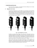
Page 7: ...that are available Figure 1 Typical Mulitport Service Terminals The MST uses CommScope DLX adapters for the optical ports A DLX adapter consists of a standard SC adapter that is enclosed within a protective housing The housing provides sealed environmental protection for the adapter The opening to each optical port is sealed with a threaded dust cap that prevents the entry of dirt and moisture A s...

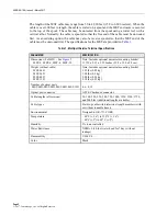
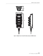
Page 8: ...ER SPECIFICATION Dimensions LxWxD See Figure 2 MST 4 MST 6 MST 8 MST 12 Note Includes optional universal mounting bracket 11 739 x 5 13 x 3 52 Inches 29 8 x 13 0 x 8 9 cm Weight without cable MST 04D MST 06D MST 08D MST 12D Note Includes optional universal mounting bracket 1 93 lbs 0 88 kg 1 98 lbs 0 9 kg 2 08 lbs 0 94 kg 2 18 lbs 0 99 kg Number of optical ports MST 04D MST 06D MST 08D MST 12D 4 6...

Page 9: ...DCP 96 159 Issue 4 March 2017 Page 3 2017 CommScope Inc All Rights Reserved Figure 2 Multiport Service Terminal Dimensions shown with UMB Installed 5 13 IN 13 0 CM 3 52 IN 8 9 CM 11 73 IN 29 8 CM 23545 A ...

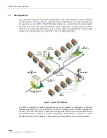
Page 10: ...ibers Drop cables transport the optical signals from each MST to the individual subscribers Figure 3 Typical FTTH Network The MST is designed for outdoor applications and can be installed in a hand hole or pedestal mounted on a utility pole or over head cable A universal mounting bracket UMB is shipped with the MST The MST meets the environmental criteria specified in the referenced specifications...

Page 11: ...cing MST stub cables must be routed to a separate splice enclosure not provided and spliced to the system distribution cable Refer to Section 3 for general cable pulling guidelines and cable installation recommendations Drop Cable Installation A fiber drop cable connects MST to the subscriber Follow local practice for pulling and installing drop cables Refer to the instructions provided with the m...

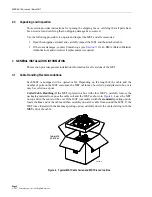
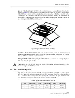
Page 12: ...formation for all versions of the MST 3 1 Cable Handling Recommendations Each MST is equipped with a optical cable Depending on the length of the cable and the number of ports on the MST enclosure the MST cable may be coiled up and placed in box or it may be coiled on a spool Coiled Cable Handling If the MST is placed in a box with other MST s carefully remove the packaging material to expose the ...

Page 13: ...mits for the distribution cable Always maintain a minimum bend radius of 6 inches during installation and 4 inches when installed Pulling the MST Cable When pulling the MST cable into place do not exceed a pulling force of 25 pounds on the optical cable 3 2 Fiber and Port Configuration Depending on the option ordered the MST is equipped with four six eight or twelve optical ports The number of eac...

Page 14: ...round mounting system that may be used for any MST or other similar products When installed the top of the hand hole enclosure is flush with the top of the ground Hand hole enclosures consist of a base unit and a top cover The base unit mounts in the ground Cables and conduit enter the base unit from the bottom Figure 6 Typical Hand Hole Mounting Pedestal Mounting at final grade Pedestal enclosure...

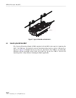
Page 15: ...g screws or construction screws Other than the fasteners no additional parts are required for pole mounting Figure 8 Typical Pole Mount Installation Strand Mounting aerial A strand mount bracket kit MST ACC M02 is available for aerial mounting the MST from an overhead strand as shown in Figure 9 The brackets mount on the UMB and are then clamped to the strand The MST snaps into the UMB 23579 A 7 I...

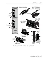
Page 16: ...MB supplied with the MST and is used for mounting the MST The UMB may be attached to various mounting surfaces using a variety of fasteners as shown in Figure 10 Multiple holes and slots are provided in the UMB to accommodate different fasteners including screws nails and cable ties Secure the UMB to the selected mounting surface using whatever fastening method is applicable 23571 A ...

Page 17: ...RAND MOUNTING THE UMB USING Deltec CABLE STRAPS STRAND MOUNT STRAND MOUNT BRACKET KIT MST ACC M02 REFER TO ADCP 96 124 FOR THE BRACKET KIT INSTALLATION PROCEDURES HAND HOLE LEDGE MOUNT HAND HOLE HANGER MOUNT HAND HOLE SWING ARM MOUNT FLAT BRACKET MOUNT HAND HOLE OR PEDESTAL 8 16 X 1 2 INCH THREAD ROLLING SCREWS FOR PLASTIC CAPPED HOLES 10 X 1 INCH SELF TAPPING SCREWS 10 X 2 INCH SCREWS WASHERS NUT...

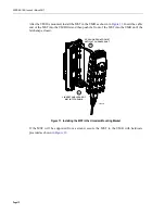
Page 18: ...B first and then push the front of the MST into the UMB until the latch snaps closed Figure 11 Installing the MST in the Universal Mounting Bracket If the MST will be supported from a strand secure the MST to the UMB with hardware provided as shown in Figure 12 23546 A 1 2 2 PUSH ON FRONT OF MST UNTIL LATCH SNAPS SHUT 1 INSERT CABLE END OF MST INTO THE UMB ...

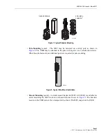
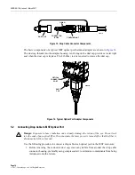
Page 19: ...or and adapter components and provide instructions for connecting or disconnecting the drop cable to from the optical ports 5 1 Connector Components The basic components of the drop cable connector are shown in Figure 13 The connector coupling nut threads onto the dust cap The O ring on the connector body provide a water tight seal when the dust cap is in place A pulling eye is provided in the end...

Page 20: ... 2 Connecting Drop Cable to MST Optical Port Use the following procedure to connect a drop cable to an optical port on the MST enclosure 1 Before removing the connector dust cap clean any debris from around the drop cable connector housing preferably using compressed air to minimize contaminants from being introduced onto the ferrule Danger Exposure to laser radiation can seriously damage the reti...

Page 21: ...ified in ADCP 96 163 5 Align the drop cable connector with the optical port as shown in Figure 15 The protrusions on the drop cable connector should line up with the arrow on the optical port Figure 15 Typical Connection of a Drop Cable To MST Optical Port 6 Insert the drop cable connector into the optical port until it slides freely into place and latches 7 Thread the drop cable connector couplin...

Page 22: ... port see Figure 15 4 Grasp the connector and pull it straight out of the adapter 5 Lbs of force or less is required to extract the connector 5 Thread the optical port dust cap into the optical port and tighten until finger tight see Figure 14 6 Thread the drop cable connector coupling nut into the drop cable dust cap and tighten until finger tight see Figure 13 6 MAINTENANCE PROCEDURES Maintenanc...

Page 23: ... local operating practices 2 Unscrew the drop cable connector coupling nut from the drop cable dust cap 3 Examine the end of the drop cable connector note the position of the protrusions on the connector see Figure 17 Figure 17 Typical Angled Connector End Face Detail 4 Locate the cleaning tape cassette that is provided with the cleaning kit 5 Open the tape shutter by squeezing the lever on the un...

Page 24: ... press too hard and do not repeat the cleaning motion with the same tape 8 Release the lever on the underside of the cassette to close the tape shutter 9 Repeat Step 4 through Step 7 until the connector has been cleaned three times 10 When the connector is clean reinstall into optical port Note The drop cable connector uses angled SC type connectors Make sure the connector end face is pointing in ...

Page 25: ...ices 2 Using a 216B key tool unthread the optical port dust cap from the optical port adapter 3 Locate the dry swabs that are provided with the connector adapter cleaning kit 4 Insert a dry swab into the adapter as shown in Figure 19 5 While applying light pressure against the connector end face rotate the dry swab 360º three times 6 Dispose of the dry swab after use 7 When connector end face and ...

Page 26: ...age 20 7 CUSTOMER INFORMATION AND ASSISTANCE To find out more about CommScope products go to www commscope com For technical assistance customer service or to report any missing damaged parts go to http www commscope com SupportCenter ...

Reviews: