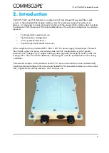
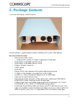


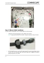


1-Port 5Gb PoE Extender Manual
19
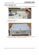
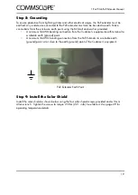
Step 8: Grounding
To ensure protection from lightning strikes and other electrical surges, the PoE extender must be
earthed. Any end device connected to the PoE extender must also be bonded to earth. Make
connections from the enclosure earth point using the M5 bolt and washer provided:
1.
A minimum 16AWG bonding connection from the Customer’s equipment earth terminal to
a reliable earth (ground) point.
2.
A minimum 16AWG bonding connection from the PoE Extender to a reliable earth
(ground) point, at or close to the earth (ground) point of the Customer’s equipment.
PoE Extender Earth Point
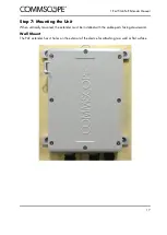
Step 9: Install the Solar Shield
Install the solar shield as shown below using the four Allen head screws provided and a 3 mm
Allen wrench. Tighten the screws to torque 2.5Nm (22.1 in-lb). See Table 4.2 on page 29 for
operating temperature details.
Summary of Contents for PFU-P-E-O-060-01
Page 1: ...860659348 Rev A 1 Port 5Gb PoE Extender Manual 860659348 Rev A October 2020 ...
Page 2: ......
Page 6: ...1 Port 5Gb PoE Extender Manual 2 ...
Page 8: ...1 Port 5Gb PoE Extender Manual 4 ...
Page 12: ...1 Port 5Gb PoE Extender Manual 8 ...
Page 14: ...1 Port 5Gb PoE Extender Manual 10 ...


