5
.
System Operation
Page 10
PowerShift User Manual Version B
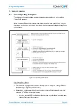
c. When input power is applied to a circuit, the module executes a startup
calibration mode only for that circuit (the other two circuits are not
impacted); it calculates the round-trip resistance between the module
output and the capacitive jumper at the far end of the cable
d. The calibration mode is approximately 30 seconds in duration, during which
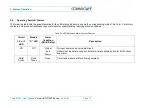
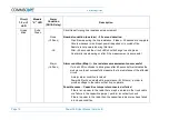
time the applicable circuit LED (1, 2 or 3) will flash green (i.e., a slow flash
with a one-second interval)
•
A red or yellow LED indicates a fault at the module level; see the next
section for more information
e. During calibration, the module outputs a varying low voltage (approximately
10 volts); this voltage is sufficiently low that it will not power on the Remote
f. When the calibration is complete, the module outputs full nominal operating
voltage to power on the Remote
g. During nominal operation, the module continuously monitors the load
current demanded by the Remote and dynamically varies its output voltage
to deliver the set-point voltage at the Remote input
h. Any time the input voltage to a module circuit falls below about 30V, the
affected circuit will re-run the initialization sequence and re-calculate the
round-trip resistance of the cable
•
NOTE
: If a circuit is operating normally and the input power is
removed, the capacitive jumper must discharge down to about 10 volts
before the initialization sequence will start. This typically occurs within
a few seconds, but if there is no remote radio connected (no load) then
it can take a minute or two for the discharge to complete and the
initialization sequence to start.
i. The three circuits in the module operate independently from one another.
Power cycling the input to one circuit of a module has no impact on the
other two circuits.
j. The module “X” LED will continue to be solid green if there is input power
to at least one of the three module circuits
5.2.
LED Status Indicators
The following is a description of the module LED status indicators.
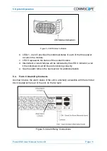
a. There are four LED status indicators on each PowerShift Module, they are
labelled: 1, 2, 3 and X


