ADCP-92-309 • Issue 4 • July 2016
Page 10
© 2016
CommScope
. All Rights Reserved.
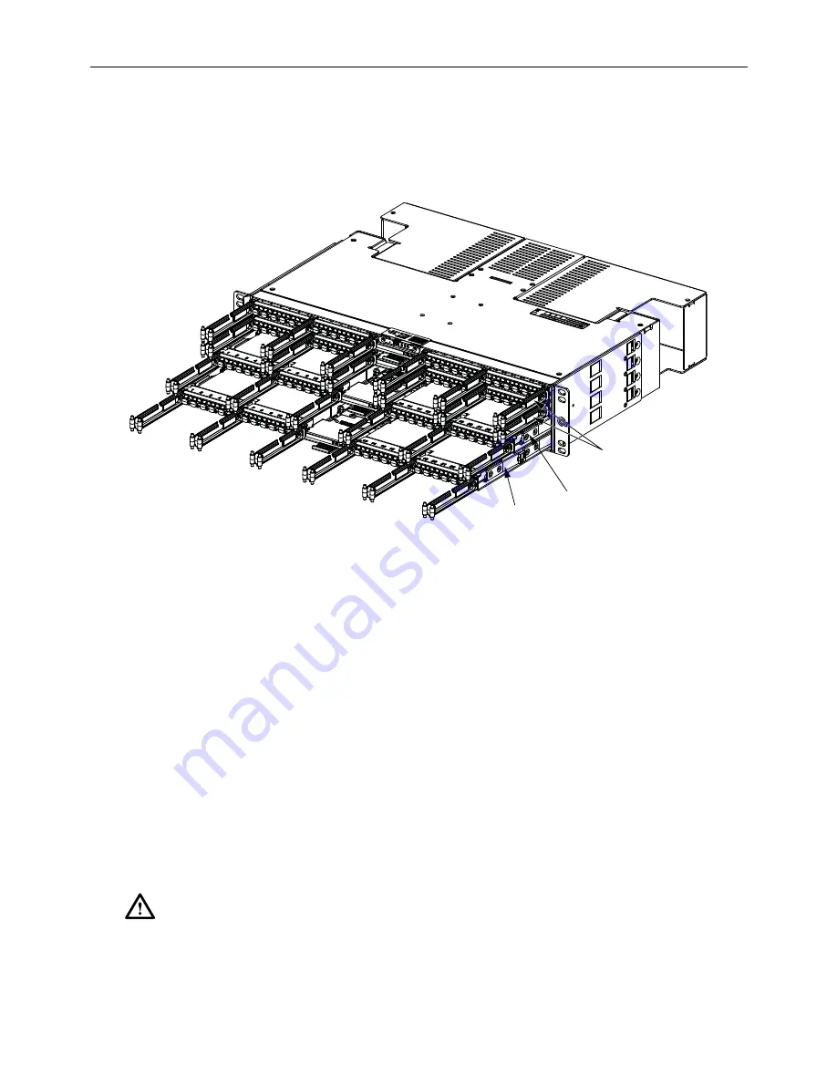
When the blade is fully pushed into the chassis it is connected to the back plane. The blade
remains connected to the back plane at the first detente position. When the blade is pulled out to
the second detent the blade is disconnected from the back plane. When the blade is fully pushed
into the chassis it is reconnected. Refer to
Figure 6
.
Figure 6. Fiber Blade Detents
Install blades starting at the bottom, filling the remaining slots until the chassis is full.
1. Align blade edges with slot in chassis and slide into chassis from the front.
2. Blade will snap into the chassis when it is inserted about half way.
3. Press in on the Latches on each side of the blade and push in to next detent.
4. Push in on second set of latches and push blade all the way into the chassis.
5. When blade is pushed all the way into the chassis it is connected to the back plane.
6. Route incoming fibers to chassis. See
Section 3.6 Cable Installation
.
a. If Managed Fiber Cables are used attach cables to appropriate adapters.
b. If LC to MPO blades are used attach MPO cables to appropriate adapters.
7. Make sure to route the Managed Fiber Cables right or left as determined by the side of the
chassis the cables are entering from. Route Managed Fiber Cables through cable
management system to the front of the chassis and attach to proper adapters.
Caution: If blades are in one of the detent positions when fiber connections are made, make
certain that there is enough slack in the cable so that when blade is pushed in fiber bend radius
is not compromised.
MODULES FULLY
INSERTED
MODULE
AT 3-INCH
DETENT
MODULE
AT 6-INCH
DETENT
24752-A


