ADCP-92-309 • Issue 4 • July 2016
Page 8
© 2016
CommScope
. All Rights Reserved.
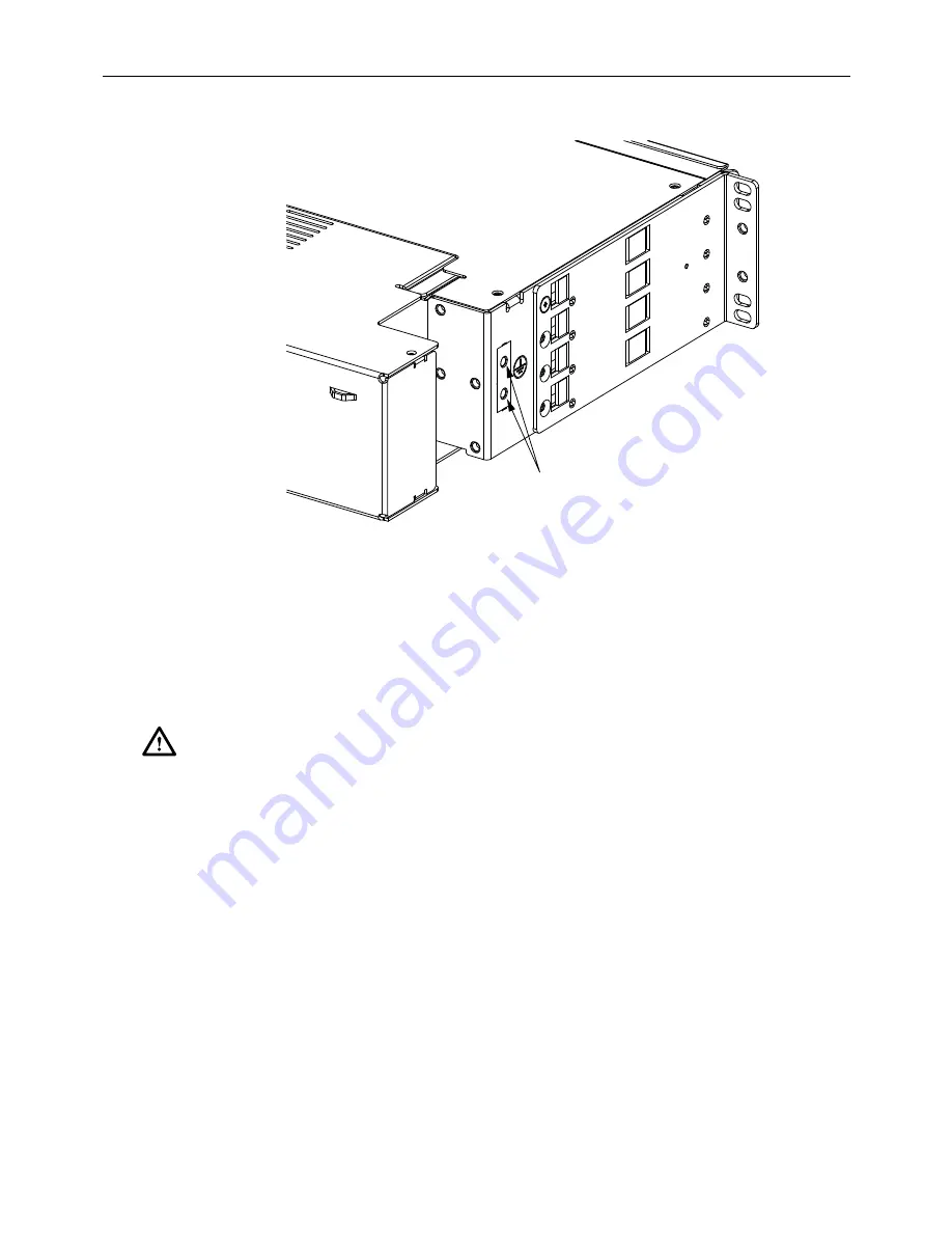
Figure 4. 2RU Chassis Ground Location
4. Connect the other end of the ground wire to the earth ground conductor. Ensure this
connection is made using methods and hardware that meets all applicable local and
national electrical codes.
3.4
Power Cabling
Each chassis controller has two potential power sources. One is a Power over Ethernet (PoE)
source, and the second is AUX power from an external source.
A RJ-45 connection on the controller is required to interface the Ethernet to the end user. Connect
an Ethernet cable to the RJ-45 port. If this connection originates at a PoE switch the controller is
powered over the Ethernet connection. If only a PoE connection is made to the controller, the PoE
connection powers the controller. The AUX power connection is not required for power. If both a
PoE switch and an AUX power source connection is made to the controller, the AUX power
connection powers the controller. If a standard Ethernet (non PoE) connection is made to the
controller, the AUX power connection is required to power the controller.
A PoE switch and an AUX power supply can simultaneously be connected to the controller
module. A PoE switch is designed to shut power off when the presence of another power source
(AUX power) is present. If power is not provided through the AUX port the controller assumes
a PoE switch is the voltage source. During the AUX power application to the controller the
Caution: When connecting the equipment to the power sources, check the equipment nameplate
rating to avoid overloading circuits which may cause damage to over-current protection devices
and supply wiring.
GROUND
LOCATION
24739-A


