TECP-90-814 • Rev C • October 2020
Page 38
© 2020
CommScope
. All Rights Reserved.
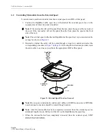
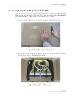
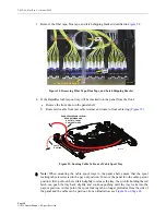
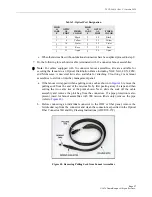
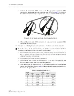
Figure 49. Removing Pipes from 900 mm Fanout Assemblies
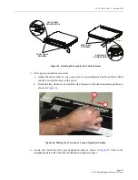
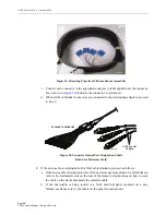
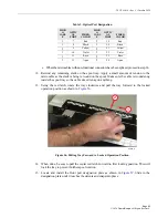
c. Connect each connector to the appropriate adapter. A label applied near the connector
boot, shown in
, indicates the connector’s optical port.
d. When all the individual connectors are connected to the terminating adapters, proceed
to step 9.
Figure 50. Connector Optical Port Designation Labels
(Shown for Reference Only)
8. If the microcable is terminated with a NG4 cabled module, proceed as follows:
a. If the microcable is being routed to a NG4 universal panel mounted on a QNG4 frame,
refer to the laminated cards on the rear of the frame for instructions on how to route
the cable on the frame and install the cabled module.
b. If the microcable is being routed to a NG4 universal panel mounted on a non-
NG4access frame, refer to the labels on the panel for instructions.
PIPE
25176-A
1
2
3
OPTICAL PORT
LABELS
24596-A
SC FANOUT ASSEMBLIES


