www.commscope.com
860452168
Instruction Sheet
Page 15 of 21
RoloSplice
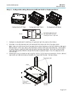
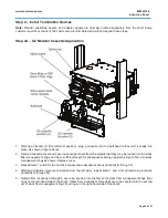
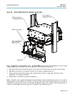
1. Assemble components for mounting in the illustrated position, if required. See figure above.
2. Install plastic fasteners into splice organizer mounting panel as shown.
3. Assemble base of
RoloSplice
onto plastic fasteners and push in plungers to fasten.
Note:
The
RoloSplice
is designed to accommodate all splice trays sold by
SYSTIMAX
, including:
Mechanical (Rotary)
Fusion
Mass Fusion.
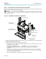
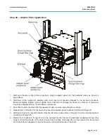
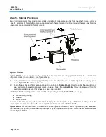
Splice trays may be assembled onto pivoting trays of
RoloSplice
by slightly bending pivot tray sufficiently to
allow splice tray to be snapped in between engaging features.
RoloSplice
may be temporarily removed from splice organizer mounting panel (by releasing the plastic
fasteners) for splicing operations or splice tray/pivot tray assemblies may individually removed and populated
with splices before being placed back into the assembly.
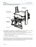
UHD Stackable Splice Trays
Notes
:
•
Stackable splice tray kit (MID 760148502) is ordered separately from shelf. Refer to instructions enclosed
with that kit for all details not covered here.
•
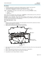
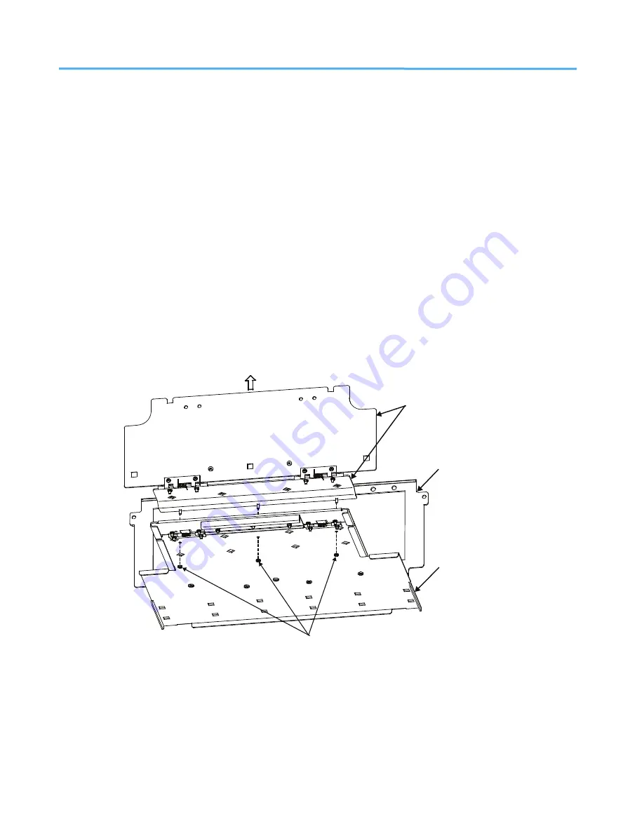
Hinged rear panel assembly must be removed, as shown below.
•
Sliding function of shelf must be defeated when using these trays.
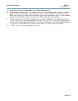
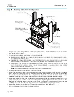
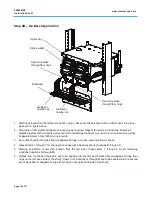
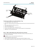
1. Slide internal mechanism (floor) of shelf fully out to expose three locknuts (as shown on previous page) and
remove them.
2. Remove components from shelf and return internal mechanism to closed position.
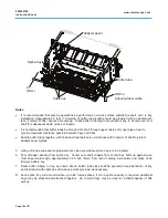
3. Remove all fiber management rings from floor area behind bulkhead.
4. Snugly fasten two quick-release fasteners on bulkhead.
Bulkhead
Remove
components
Sliding internal
mechanism (floor)
Remove locknuts
(3 places)

