www.commscope.com
860543388
Instruction Sheet
Page 11 of 19
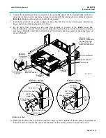
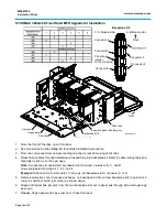
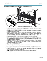
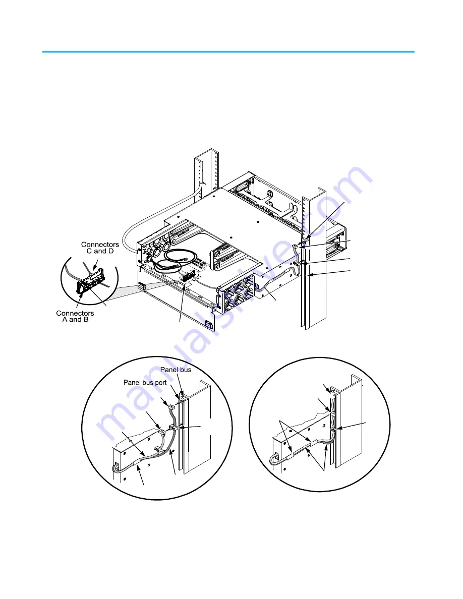
6. Connect the keyed female 10-pin connector on the panel bus jumper into the nearest cable bus port on
panel bus as shown on the next page. Jumper is secured with flat retainer clips on outside of side wall.
Important:
Make sure the jumper connector is fully seated.
7. Install spare port built into jumper cordage into panel bus frame by turning it at an angle, inserting into
frame, and turning it back perpendicular to frame.
8. 4U HD MPO fiber shelves use two panel bus jumpers to connect to the
iPatch
panel bus.
The 2nd panel bus jumper’s 10-pin connector plugs into the spare bus port on the 1st panel bus jumper,
as shown in Detail
B
. Insert both connectors and 2nd jumper’s spare bus port into panel bus frame as
shown in Detail
C
.
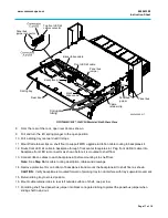
9. Open rear door.
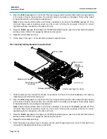
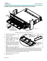
10. Reach in shelf from back to pull ribbon cables to back. Connect upgrade kit ribbon cables to backplane kit.
Connect loose end of panel bus jumper to backplane kit while holding it close to opened back door.
Detail B – 4U only
Detail C – 4U only
Panel bus
jumper
Panel bus jumper
Panel bus
jumper
Spare
bus port
Retainer clip
1st 10-pin connector
2nd 10-pin
connector
Spare bus port
10-pin connector
Panel bus
Spare
bus
port
Panel bus jumpers
1st 10-pin
connector
2nd 10-pin
connector
Retainer clips
Panel bus
jumper connector
Detail A
Backplane
cover
Panel bus port
(max. of 5 connectors
per bus port, start
a new chain with
every 6th connector)
860543388-010


