860543388
Instruction Sheet
www.commscope.com
Page 12 of 19
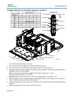
Note:
See Step
3b
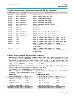
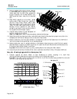
for panel bus jumper termination table and connection diagram.
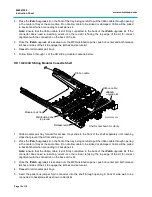
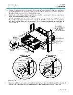
11. Remove paper cover to expose adhesive on backplane kit. After making connections with ribbon cables and
panel bus jumper, mount backplane to shelf floor in available space in back of shelf.
SYSTIMAX 360G2 1U and 2U Fixed Shelves and 1U Internal Sliding MPO Shelf
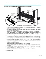
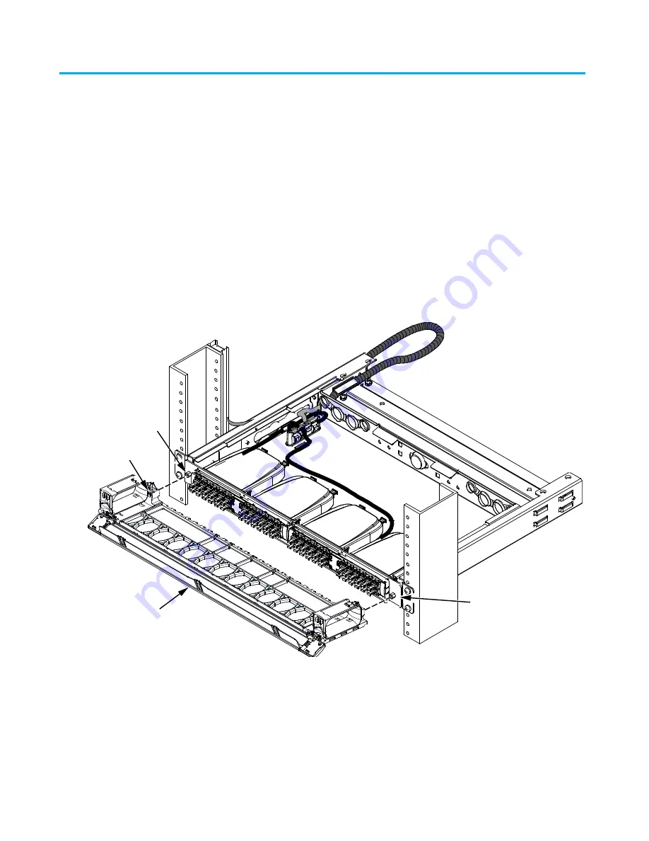
Remove Patch Cord Trough
1. From the rear of rack, remove any cable retainers and provide enough cable slack to move shelf forward.
2. From the front of the rack, remove front door.
Note:
Open the door on the patch cord trough by gently pressing both upper corners to
release the latches. Then lift the door off the trough.
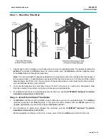
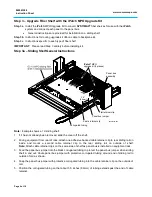
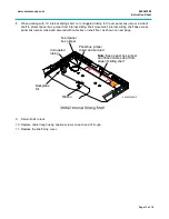
3. Trough is positioned on shelf so that indentions behind captive screws rest on the standoffs.
4. Using a Phillips head screwdriver, loosen the captive screw on each end of trough to release it from shelf.
Note:
If removing the trough on a sliding shelf, pull the shelf out enough to support the faceplate from behind
before loosening the captive screws.
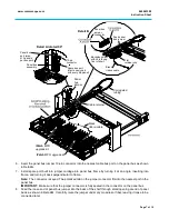
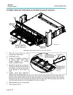
5. Carefully remove shelf from rack and slide forward.
6. Remove top cover by sliding toward front of shelf.
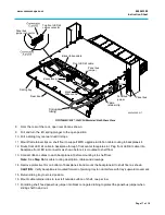
7. Refer to General Instructions,
Steps 3a
and
3b
, for detailed installation procedure.
Note:
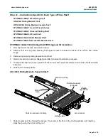
Shelf has excess panel bus jumper coiled and secured into 3” (76mm) loops with cable ties on
shelf floor.
Captive screw
(2 places)
Standoff
Standoff
Trough
860543388-011


