background image

860543388 
Instruction Sheet 


www.commscope.com 


Page 16 of 19 

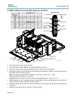
SYSTIMAX 360G2 UHD 1U/2U/4U Modular Shelf MPO Upgrade Kit Installation 


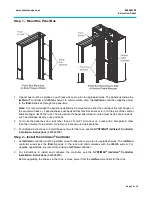
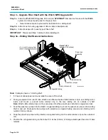
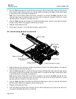
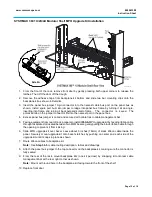
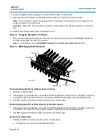
1.  From the front of the rack, pull  

a sliding tray shelf forward.  

2.  Lift the patch cover. 

3.  Prepare to install MPO upgrade kit 

by feeding black  ribbon cable 
through faceplate slot located 
between two MPO bezels. 

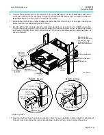
4.  Slide MPO upgrade kit over bezels. 

Securely mount onto bezel’s latches 
by pushing on center and each side 
of the upgrade kit until it snaps in 
place. 

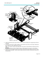
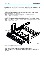
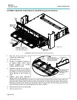
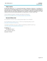
5.  Replace center fiber patchcord 

divider with front LED kit as shown in 
Detail 

A

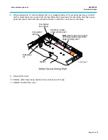
. Use a small flat-blade screwdriver to pry the divider out and snap the front kit in place. Place the 

back of front kit (without LED) into tray slot first, then snap the front into place as shown. When placing 
the LED kit into the center divider slot, insert back of kit into back notch and then gently snap the front 
(with LED light) into place to avoid breaking the front tab on LED kit.  

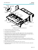
6.  Slide the sliding tray to stored position. 

7.  Close the patch cover. 


Cover

iPatch

®

 MPO

upgrade kit

iPatch

®

 MPO

upgrade kit

Replace center fiber
patchcord divider with
front LED kit (Detail A).

Front
LED kit

LED kit
cable

860543388-015


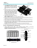
Detail A (rotated 180°)

Shelf front

Place the back of

front kit into raised tray

slot first, then snap

the front into place

Tab at back of front

kit hooks under

raised slot in patch

cord trough

Front LED kit

860543388-016

Summary of Contents for SYSTIMAX 360 iPatch 360G2-iP-32-MPO-SD-KIT-5PK

Page 1: ...the SYSTIMAX iPatch shelf in an existing iPatch System the imVision Controller must be running firmware version 10 3d or later The System Manager software used to manage the system must be version 7 3 1 or later We recommend that you upgrade the System Manager software before installing the shelf Ordering information is listed below Material ID Part No Description 760169151 360G2 iP 32 MPO SD KIT ...

Page 2: ... parts against the parts list below Quantity Description 360 iPatch Upgrade Kit 32 MPO 1 kit 760169151 360 iPatch Upgrade Kit UHD 32 MPO 1 kit 760169169 2 2 iPatch MPO assembly 1 1 Backplane kit and cover 2 Backplane clip 1 MPO front kit with LED cable 8 8 Flat retainer clip 2 2 Panel bus jumper cable 2 2 Ribbon cable assembly 2 2 Cable retainer clip 1 1 Corrugated tubing 32 32 Dust cap 1 1 Instru...

Page 3: ...144 duplex LC ports or 96 MPO ports 760227314 UD 4U Ultra density 4U sliding modular cassette shelf accepts 24 InstaPATCH 360 modules or MPO panels up to 288 duplex LC ports or 192 MPO ports Important Limits for iPatch shelf and panel connections iPatch MPO fiber shelves are limited to a maximum number of rack units RUs and will not support a fully populated rack or cabinet iPatch MPO fiber shelve...

Page 4: ...eable components and any damage to the anti tamper label or removal of top cover or front adapter mounting panel will void the warranty Fiber optic trunk cable and jumper performance is sensitive to bending pulling and crushing Minimum bend radius must be maintained during installation per the manufacturer s specification Appropriate pulling socks must be used during installation and pulling force...

Page 5: ...nserts nuts and bolts 2 To mount the panel bus on a rack other than a 7 foot 2 1m rack or on a rack with a hole pattern other than the universal hole pattern contact your local account representative 3 For detailed instructions to install the panel bus for the rack see the SYSTIMAX imVision Controller Installation Instructions 860526839 Step 2 Install the imVision Controller 1 An imVision controll...

Page 6: ...nt from rear of rack attach one adhesive backed cable retainer clip to rear sliding rail on inside and mount a second cable retainer clip to the rear sliding rail on outside of shelf Note Attach cable retainer clips on the same side of shelf as panel bus is installed on equipment rack 3 Feed the panel bus jumper into the black corrugated tubing to protect the panel bus jumper when sliding shelf in...

Page 7: ...ctor is fully seated in the connector on the panel bus 8 Feed the loose end of panel bus jumper into the back of the shelf through small opening at end of panel back as shown in Detail B Carefully route the jumper under any modules or fiber leaving it loose to be connected later Corrugated tubing Black ribbon cable iPatch MPO upgrade kit iPatch MPO upgrade kit Panel bus jumper Cable retainer 10 pi...

Page 8: ...etainer clips and place on shelf floor as needed Eight flat retainer clips are provided for each row of a shelf Insert each ribbon cable into flat retainer clip to route any slack ribbon cables on shelf floor Important Be careful not to bend or pull any existing fibers while routing the ribbon cables 15 Insure the panel bus strip is installed to the rack or cabinet as described in Step 1 Replace s...

Page 9: ...emove front door by gently pressing both upper corners to release the latches Then lift the door off the trough 3 Remove top cover by sliding toward front of shelf 4 Refer to General Instructions Steps 3a and 3b for detailed installation procedure 5 To replace the shelf s top cover position between lower and upper sets of tabs on each side of shelf and slide into place 6 Slide shelf to stored posi...

Page 10: ...ccess Trays slide to the front of the shelf separately until reaching stops that prevent them from sliding out 2 Place the iPatch upgrade kit on the front of the tray being careful to pull the ribbon cable through opening in the center of tray at the same time Do not allow cable to be kinked or damaged Cable will be pulled to back of shelf when connecting to backplane kit Note Ensure that the ribb...

Page 11: ...spare bus port on the 1st panel bus jumper as shown in Detail B Insert both connectors and 2nd jumper s spare bus port into panel bus frame as shown in Detail C 9 Open rear door 10 Reach in shelf from back to pull ribbon cables to back Connect upgrade kit ribbon cables to backplane kit Connect loose end of panel bus jumper to backplane kit while holding it close to opened back door Detail B 4U onl...

Page 12: ...ord trough by gently pressing both upper corners to release the latches Then lift the door off the trough 3 Trough is positioned on shelf so that indentions behind captive screws rest on the standoffs 4 Using a Phillips head screwdriver loosen the captive screw on each end of trough to release it from shelf Note If removing the trough on a sliding shelf pull the shelf out enough to support the fac...

Page 13: ...nt Internal sliding shelf has excess panel bus jumper coiled and secured with cable ties on shelf floor as shown on next page 9 Return shelf to rack 10 Replace cable trough using captive screws on each end of trough 11 Replace the shelf s top cover Feed panel bus jumper Ribbon Note Keep panel bus jumper and ribbon cables clear from edge of sliding shelf Corrugated tubing Panel bus jumper coiled an...

Page 14: ...C and D Rows are labeled from top as 1 2 3 and 4 Example Ribbon cable from module 1 C D plugs into backplane kit 2 connector C or D 5 Remove protective cover to expose adhesive on backplane kit Mount two backplane kits one kit per 2 rows to shelf floor at left rear corner as shown above 6 Route both panel bus jumpers from the two backplane kits out to panel bus through side wall openings as shown ...

Page 15: ...d with cable ties to cable management bar 5 Facing equipment from rear of rack prepare to install iPatch MPO upgrade kit by feeding ribbon cable through faceplate slot located between two MPO bezels gently pulling the black ribbon cable through the opening to prevent it from kinking 6 Slide MPO upgrade kit over bezel Leave about 3 inches 76mm of slack ribbon cable inside the panel Securely mount u...

Page 16: ...driver to pry the divider out and snap the front kit in place Place the back of front kit without LED into tray slot first then snap the front into place as shown When placing the LED kit into the center divider slot insert back of kit into back notch and then gently snap the front with LED light into place to avoid breaking the front tab on LED kit 6 Slide the sliding tray to stored position 7 Cl...

Page 17: ... floor Note See Step 3b for cable routing description tables and drawings 14 Remove protective film on bottom of backplane kit and mount the backplane kit to shelf floor as shown CAUTION Verify backplane is mounted forward of pivoting tray to not interfere with tray s upward movement 15 Return sliding tray to stored position 16 Mount cable retainer clips to rear left outside surface of shelf one p...

Page 18: ...IMAX imVision Controller User Guide 860547876 Step 5 MPO Upgrade Kit Removal Removing Upgrade Kit on sliding shelves or trays 1 Slide tray or shelf forward 2 Use spudger to pry release tab on one side of the MPO upgrade kit Using wire tip on spudger pull tab out to release kit from bezel latch as shown Swing away carefully to disengage center and opposite side 3 Pull MPO upgrade kit forward 2 inch...

Page 19: ...certified in accordance with international standards including ISO 9001 TL 9000 and ISO 14001 Further information regarding CommScope s commitment can be found at www commscope com About Us Corporate Responsibility and Sustainability Contact information Visit our website or contact your local CommScope representative for more information For technical assistance customer service or to report any m...

Reviews: