860543388
Instruction Sheet
www.commscope.com
Page 8 of 19
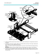
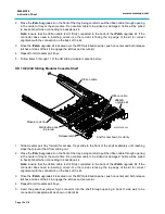
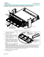
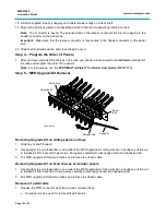
9. Facing equipment from front of rack, prepare
to install
iPatch
MPO upgrade kit. Feed black
ribbon cable from the rear of the upgrade kit
through faceplate slot located between two
MPO bezels as shown, ready to be connected
later.
10. Slide MPO upgrade kit over bezel, gently
pulling ribbon cable through the opening to
prevent it from kinking. Route ribbon cable
back under patch cords. Leave about 3 inches
(76mm) of slack ribbon cable inside the panel.
Securely mount upgrade kit onto bezel’s
latches by pushing on center and each side of
the upgrade kit until it snaps in place.
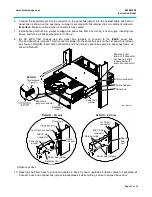
11. Connect ribbon cables to each backplane kit
before mounting it to shelf floor.
Note:
See
Step 3b
for cable routing description, tables and drawings.
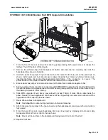
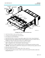
12. Attach the panel bus jumper previously routed into back of shelf to the panel bus jumper connector on the
backplane kit, as shown, making sure the connector is fully seated.
13. Remove protective cover to expose adhesive on backplane kit. Mount the backplane kit to shelf floor at
rear corner closest to the panel bus, or any available space.
14. Remove protective cover to expose adhesive on flat retainer clips and place on shelf floor as needed.
Eight flat retainer clips are provided for each row of a shelf. Insert each ribbon cable into flat retainer clip
to route any slack ribbon cables on shelf floor.
Important:
Be careful not to bend or pull any existing fibers while routing the ribbon cables.
15. Insure the panel bus strip is installed to the rack or cabinet as described in Step 1. Replace shelf cover.
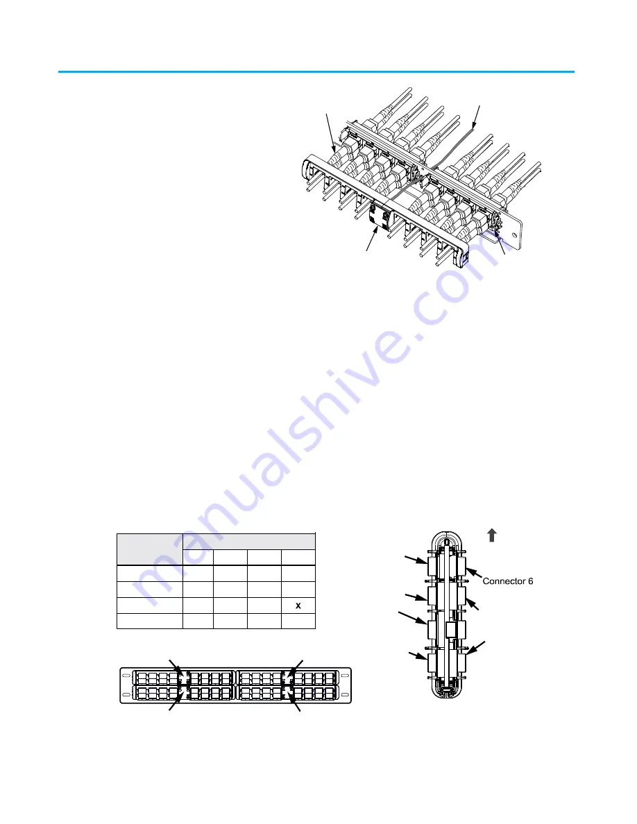
Step 3b – Routing Upgrade Kit to Backplane Kit
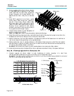
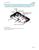
1. Connect upgrade kit ribbon cables to each backplane kit before mounting it to shelf floor.
Use the termination table below to guide connections on a 2U distribution panel.
Important:
The ribbon cable connector has a red dot on top of the connector. Always attach the connector
with this red dot facing the top edge of kit.
8
4
7
3
5
1
6
2
5-8
1-4
5-8
1-4
8
4
7
3
5
1
6
2
8
4
7
3
5
1
6
2
5-8
1-4
5-8
1-4
8
4
7
3
5
1
6
2
8
4
7
3
5
1
6
2
5-8
1-4
5-8
1-4
8
4
7
3
5
1
6
2
8
4
7
3
5
1
6
2
5-8
1-4
5-8
1-4
8
4
7
3
5
1
6
2
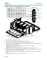
1U/ 2U Backplane Termination Table
2U Distribution Panel
BACKPLANE CONNECTOR
Distribution
Panel
Row/ Column
1AB
1CD
2AB
2CD
1
2
3
4
X
X
X
1AB
2AB
Modules are 1A, 1B, 1C, 1D, 2A, 2B, 2C, 2D
1CD
2CD
Backplane Kit
C, D Module side
Connector 5
Connector 3
Connector 4
Connector 2
Panel bus
jumper
connector (Bus)
Connector 1
Front
A, B Module side
860543388-007
Upgrade kit
Ribbon cable
Bezel latch
Patch cord
860543388-006


