background image


- 17 - 

4.4.3.


When connecting a phone with a 
2.5mm connection or a Nokia

TM


brand connector, use the C-AT 
supplied cable with the appropriate 
2.5, (or Nokia

TM

) connector and RJ-

10 connector. 

4.5.


Using a Nextel

TM

 phone in 

DirectConnect

TM

 mode. 

4.5.1.


When connecting a Nextel

TM


connect the phone as you would an 
L-M-R. 

4.5.2.


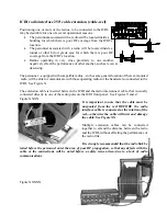
Install the radio-end of the ICRI 
interconnect cable onto the 
accessory jackat the bottom of the 
phone, as you would install any 
accessory (i.e.: a shoulder speaker / 
microphone) 


FIGURE 29: CONNECT TO NEXTEL

TM

 DIRECT 

CONNECT

TM


4.5.3.


Attach the other end of the cable to 

any


of the 

LAND MOBILE RADIO 

INTERFACE jacks

.  

NOTE:  The Nextel speaker and mic will be 
disabled while the phone is connected to the 
ICRI. 

Summary of Contents for ICRI

Page 1: ...ger Bacon Drive Reston Virginia 2 0 1 9 0 5 2 0 2 800 229 3925 voice 703 471 4428 fax http www c at com internet Revision N Setup and Operating Procedures ICRITM Incident Commanders Radio InterfaceTM A Rapidly Deployable Radio Interoperability Solution ...

Page 2: ...IC COUPLER 13 FIGURE 19 ACOUSTIC COUPLER TO CELLULAR PHONE 13 FIGURE 21 TELEPHONE INTERFACE JACK 14 FIGURE 22 TELELPHONE CONNECTOR ASSEMBLY DRAWING 14 FIGURE 23 CELLULAR PHONE CONNECTOR VIEW 1 Error Bookmark not defined FIGURE 24 CELLULAR PHONE CONNECTOR VIEW 2 15 FIGURE 25 RJ 10 JACK 16 FIGURE 26 RJ 10 CABLE FOR NOKIATM 16 5 0 LINKING ICRIS 18 FIGURE 28 TWO LINKED ICRIs 18 FIGURE 29 INTERFACE JAC...

Page 3: ...ond talk group Talk group selection is controlled by the switches about each radio port Two ICRIs can be rapidly linked together without hand tool and or adjustments An interconnect cable may be part of this kit or is readily available A 250 extension cable for radio interface may be supplied with this kit The extension cable permits a radio to be placed at this distance from the ICRI This may use...

Page 4: ...nformation battery status in particular a reliable indication of a low voltage condition Note that if eight AA batteries are used the ICRI will continue operate to nominally for at least 2 hours after the OK LED is extinguished and the LOW LED has lit and then extinguished batteries will provide a reduced duty cycle due to low quality poor storage conditions before use and or low temperature durin...

Page 5: ...other more than 1000 Turn the knob show in FIGURE 1 counter clockwise be sure to close the purge valve after the pressure is released turn clockwise or the case will not be waterproof even with the lid latched FIGURE 1 ICRI CASE OUTSIDE 1 2 The Pelican case will appear as in FIGURE 2 with radio interface cables located in the front recess FIGURE 2 ICRI CASE INSIDE ...

Page 6: ...he rear of the pouch The internal strap prevents the ICRI from falling through the open zippered compartment 1 5 Abbreviated set up instructions are printed onto the top cover of the ICRI assembly Connector information for radio telephone and power interconnect cables is printed on the bottom of the ICRI assembly Refer to Appendices B and C FIGURE 3 PLACEMENT INSIDE CASE FIGURE 4 ICRI WITH OPTIONA...

Page 7: ...wing instructions FIGURE 5 FIGURE 6 FIGURE 8 FIGURE 7 and FIGURE 9 FIGURE 5 BATTERY INSTALLATION DRAWING FIGURE 6 OPTIONAL BATTERY CASE AND ADAPTER The battery housing is comprised of two parts the exterior case and an internal tray NO TOOLS ARE NEEDED TO REMOVE THE TRAY AND REPLACE THE BATTERIES ...

Page 8: ... To reinsert the tray make sure the tray s key goes in the matching slot side of the case FIGURE 6 Insert the tray into the housing from the bottom end of the case pushing the tray until it locks into place FIGURE 8 2 1 5 To reinstall the assembled battery pack onto the adapter align the slots on the top of the battery pack with the slide rails on the adapter Slide the battery pack onto the adapto...

Page 9: ...irst 2 2 3 Be sure that each housing cap is locked into place BY TURNING 2 2 4 After installing the batteries verify the batteries are installed correctly by turning on the ICRI the GREEN LED should be lit Please contact C AT for replacement caps if necessary NOTE 1 C AT RECOMMENDS THE USE OF NEW ALKALINE BATTERIES SUCH AS DURACELL OR EVEREADY RECHARGEABLE BATTERIES AND THOSE OF UNKNOWN ORIGIN WIL...

Page 10: ...ection is made so that the jack s locking blades slide between the blades on the plug and the body of the plug 2 3 3 Connect the assembled cable to the external DC source 2 3 4 Connect the adapter s plug to the jack labeled DC INPUT Note Align the plug s key with the jack s keyway before attempting to insert the plug 2 3 5 To remove the plug hold the fluted part of the plug s barrel and pull strai...

Page 11: ...ot be used where the cables or converter can become wet 2 4 2 Connect the power cord to the converter and to the DC source 110 120V 60Hz 2 4 3 Connect the adapter s plug to the jack labeled DC INPUT Note Align the plug s key with the jack s keyway before attempting to insert the plug 2 4 4 To remove the plug hold the fluted part of the plug s barrel and pull straight out FIGURE 13 ICRI WITH EXTERN...

Page 12: ...a shoulder speaker microphone 3 1 1 Tightening any locking screws is optional but it is important that the connector be firmly seated against the radio so that good electrical contact is made 3 1 2 FIGURE 15 3 1 3 Attach the other end of the cable to any of the LAND MOBILE RADIO INTERFACE jacks labeled 1 2 3 4 and 5 FIGURE 14 and 3 1 4 FIGURE 16 NOTE The plug on the cable and the jack are keyed Be...

Page 13: ... 10 FIGURE 16 TWO RADIOS CONNECTED TO ICRI ...

Page 14: ...cannot be turned further FIGURE 17 FIGURE 17 JACK ASSEMBLY DRAWING 3 1 6 To remove the connector for cable storage push inward on the locking ring and turn the ring counter clockwise to release the locking mechanism Then pull the connector straight out of the jack Hold the chrome barrel of the connector rather than the cable ...

Page 15: ... the audio 3 3 1 Connect the local handset to the jack on the front of the ICRI labeled HANDSET The jack on the handset is similar to those provided for the radio cables The handset connector contains more pins and is designed to be the only cable used in the HANDSET jack 3 3 2 After connecting the handset set the volume knob to mid position set the talk group switches located directly above the c...

Page 16: ...lastic strap over the handset cell phone 4 1 5 Position the RED pad directly over the microphone labeled TO MOUTH PIECE on its cable and secure by stretching the elastic strap over the handset cell phone Based on the design of the cellular telephone to place an out going call may require moving the transducers in order to access the cell phone s keypad FIGURE 19 ACOUSTIC COUPLER FIGURE 20 ACOUSTIC...

Page 17: ...FACE JACK 4 1 11 When the called party answers use the portable radio s throat mic or a headset and begin to converse with called party 4 1 12 To remove the connector for cable storage push inward on the locking ring and turn the ring counter clockwise to release the locking mechanism Then pull the connector straight out of the jack Hold the chrome barrel of the connector rather than the cable FIG...

Page 18: ...nector or the connection may be damaged 4 2 5 After the plug is fully seated on the jack the locking ring on the plug should be turned clockwise until the ring cannot be turned further FIGURE 23 4 2 6 Set telephone s earphone audio to a mid level setting following the telephone s instructions 4 2 7 After the interconnect cable from the repeater is connected to the telephone handset a dial tone sho...

Page 19: ...stening level FIGURE 26 HEADET ON CABLE REEL 4 4 ICRI phone link in optional RJ 10 connection 4 4 1 The ICRI can be configured with an optional RJ 10 jack built into the unit This jack will provide the user the ability connect a standard telephone handset without using the standard telephone port on the front of the ICRI FIGURE 27 RJ 10 JACK NOTE The RJ 10 jack and the telephone interface jack on ...

Page 20: ... a NextelTM connect the phone as you would an L M R 4 5 2 Install the radio end of the ICRI interconnect cable onto the accessory jackat the bottom of the phone as you would install any accessory i e a shoulder speaker microphone FIGURE 29 CONNECT TO NEXTELTM DIRECT CONNECTTM 4 5 3 Attach the other end of the cable to any of the LAND MOBILE RADIO INTERFACE jacks NOTE The Nextel speaker and mic wil...

Page 21: ...til the ring cannot be turned further 5 2 4 To remove the connector for cable storage push inward on the locking ring and turn the ring counter clockwise to release the locking mechanism Then pull the connector straight out of the jack Hold the chrome barrel of the connector rather than the cable 5 3 The ICRI may also be configured to link ICRIs without relinquishing the use of the telephone port ...

Page 22: ...and place the switch above the associated post in the designated position NOTE The center position of the switch places any item connected with the associated port into a NO CONNECTION conduction without physically disconnecting the device from the ICRI 6 1 6 Turn the radios on initially place the radio volume controls at a mid position between fully counter clockwise and fully clockwise As a radi...

Page 23: ... following Green lit input voltage 8 6 or greater 6 2 4 OK LOW VOLTAGE LED D This LED indicates the following Red lit input voltage 7 5 to 8 5 volts Note If neither is lit the ICRI will operate on voltage as low as 6 5V Maximum input voltage is 20VDC 6 2 5 RADIO INTERFACE JACK 1 thru 5 E This 5 pin locking type jack is Pinout 1 Gnd 2 Audio from radio 3 Audio to radio 4 Motorola Saber AstroSaber P ...

Page 24: ... Audio FROM telephone 2 5mm plug 6 2 7 HANDSET INTERFACE JACK G This 5 pin 240 degree connector supports the handset p n 280 0125 Pinout 1 Ground 2 Electret Mic 3 PTT 4 Audio Hi 5 Audio Hi 6 2 8 HANDSET VOLUME ADJUSTMENT H Volume knob adjusts the volume output level of the attached radios to the local handset To adjust the volume of the radios use the volume adjustment on the individual radios 6 2...

Page 25: ...use with 500 9280 500 9281 TRANSIT STORAGE CASES OPTIONS Waterproof case Pelican 1550 with fitted foam insert 990 0602 Waterproof case Pelican 1600 with fitted foam insert 990 0601 TELEPHONE OPTIONS Telephone handset SAT phone INMARSAT generic acoustic coupler interface cable 179 0655 Direct connection cable to Nokia TM cellular telephone headset jack 179 0802 Direct connection cable to generic 2 ...

Page 26: ...0 MTX 820S MTX 900 Radius P 200 interface cable 179 0640 Motorola TM Spectra interface cable Y cable box so normal function of radio is not affected by ICRI link 179 0636 Motorola TM MCS 2000 interface cable Y cable box so normal function of radio is not affected by ICRI link 179 0635 Motorola TM Maxtrac interface cable 20 pin Y cable box so normal function of radio is not affected by ICRI link 17...

Page 27: ...O THE ICRI VERIFY THAT IT IS WORKING NORMALLY AND HAS A FULLY CHARGED BATTERY THEN 7 TURN ON THE RADIO S AND PLACE THE RADIO VOLUME CONTROL S IN A MID POSITION NOTE THE RADIOS DO NOT HAVE TO BE SEPARATED BY ANY PARTICULAR DISTANCE BUT 6a FOR ICRIs EQUIPPED WITH TALK GROUP SELECTION TURN OFF THE RADIO OR TELEPHONE 6 CONNECT THE RADIO INTERFACE CABLE S TO THE RADIO S OF THE KNOB S ROTATION CHANGED T...

Page 28: ...P T T ONLY 3 AUDIO TO RADIO 5 P T T SWITCHCRAFT 05CL5M RADIO INTERFACE 5 3 180 1 GND 4 2 1 5 1 5 SHIELD GND 4 FROM PHONE 2 4 2 FROM PHONE 8 3 2 5 ACOUSTIC COUPLER 3 TO PHONE 1 TO PHONE SWITCHCRAFT 15CL8M 8 7 3 6 INTERFACE 7 TO ICRI NEUTRIX SC8 QTY 1 NEUTRIX FI8 QTY 1 2 GND 1 POWER NEUTRIX BS1 QTY 2 3 8 N C NEUTRIX SR8 QTY 1 6 6 REQUIRED JUMPER 5 SHIELD GND 1 3 4 1 2 8 7 6 5 7 TO PHONE 8 FROM PHONE...

Page 29: ...CORDER MOBILE VEHICLE MOUNT RADIO RECEIVER BODY WIRE CHANNEL LINK TALK AROUND LINK TO TRUNKED REPEATER INTERFACE UP TO 1 000 TRUNKED CHANNEL REPEATER REPEATING BODY WIRE SIGNAL CABLE 1st RESPONDER BELOW GRADE OR IN BUILDING ICRI ALTERNATE APPLICATIONS ...

Page 30: ... ON BOTTOM SIDE PORTABLE OR MOBILE RADIO CAN BE USED USER INSTRUCTIONS ON TOP COVER 2 1 PORTS ARE NOT RADIO SPECIFIC 1 1 1 3 INTERFACE CABLE 3 1 UP TO 1 000 CIGARETTE LIGHTER 8 AA BATTERY PACK 1 OR OR RED BLACK ICRI WITH ATTACHMENTS 2 OR NOTE NOT TO SCALE ...

Page 31: ...54 R334 HANDSET TOT ADJ R350 4 5 R94 PHONE AC OUT R126 OUT WIRED R135 WIRED AC IN R106 SENS IN R129 TAIL R339 IN R188 R307 R270 R286 R303 R318 JP18 JP17 WITHOUT JUMPER LONG BLOCKING 2 SEC WITH JUMPER ON SHORT BLOCKING 0 8 SEC FUNCTION OF JUMPERS J19 T0 J23 STANDARD NOTE TC1 TC6 ARE TEST CONNECTIONS DO NOT INSTALL JUMPERS 1 12 5 8 4 1 2 11 ...

Page 32: ...mpers on the ICRI will respond to a new voice signal approximately 0 8 seconds after the last transmission has ended This is the standard configuration With the jumper removed this time is extended to approximately 2 seconds During this time no new PTT can be initiated by any input except the TIME OUT TIMER DEFEAT With this jumper off the telephone or radio input channel will be temporarily disabl...

Page 33: ... monitor both talk groups simultaneously FIGURE 36 To utilize the speaker function connect the supplied speaker cable to one of the speaker jacks and the input jack of your amplified speaker FIGURE 37 Operate your speakers as normal using their external power source and on off function to control volume level and output The ICRI will function as normal and does not require any modifications FIGURE...

Page 34: ... radiate radio frequency energy and if not installed and used in accordance with the instructions may cause harmful interference to radio communications However there is no guarantee that interference will not occur in a particular installation If this equipment does cause harmful interference to radio or television reception which can be determined by turning the equipment off and on the user is ...

Page 35: ...nother negatively effect the performance of other another such as receiver desensing The personnel equipped with compatible radios in the same general location of the reel mounted radio will be able to communicate with those operating radios or the handset also connected to the ICRI See Figure X The extension cable is inserted between the ICRI and the radio interconnect cable that is usually conne...

Page 36: ...Place the radio on the right angle support and secure it in place with the VelcroTM strap NOTE If the cable will be used to place a radio at a high point on a building roof hill or tree top to enhance the operating range of the radio to a remote location then the it may be preferable to have the cable reel located beside the ICRI and the radio connected to the unspooled end of the cable NOTE Multi...

Reviews: