background image

Community ENTASYS Installation/Operation Manual — Page 12  

I N T R O D U C T I O N  

Thank you for selecting Community ENTASYS Column Line Source Loudspeakers.  ENTASYS features 

controlled, narrow vertical directivity with wide horizontal coverage.  The ENTASYS Full-Range loudspeaker and 
Low Frequency loudspeaker may be combined in several ways to yield outstanding performance for a wide 
range of applications.  They are easy to install and provide unparalleled sound quality in a loudspeaker of this 
type. 

This manual is intended to help you install and use ENTASYS loudspeakers safely and effectively.  It 

provides useful information to help you obtain the best performance, sound quality, and reliability from your 
ENTASYS system.  We’ve provided a series of Quick-Start diagrams to enable you to operate your 
loudspeakers immediately if required; however, we recommend that you read this manual to help insure that 
your ENTASYS installation meets the highest possible standards.  


ENTASYS Features and Technology 

ENTASYS loudspeakers offer numerous features and technology that provide unprecedented sonic 

quality and installation flexibility.  Some of these include: 

• 

Unique three-way full-range line array column with advanced passive crossover technology 

• 

Patent-pending Compact Ribbon Emulator high frequency elements provide narrow, well-behaved vertical 
directivity control 

• 

Midrange and high frequency drivers use sealed polymer frames and diaphragms for inherent weather- 
resistance  

• 

Low frequency drivers have a 100% epoxy impregnated cone with a large polymer dust cap covering the 
voice coil for weather resistance 

• 

DYNA-TECH protection circuitry helps to minimize damage to drivers 

• 

Heavy gauge extruded aluminum enclosure with power coat finish and gasket sealed, impact resistant nylon 
end caps are weather-resistant 

• 

Protective steel grilles covered with rugged powder coat finish 

• 

Multiple brackets and suspension options to suit almost any application 

• 

Seamless array ability, both acoustically and cosmetically 

• 

A large three column array can be driven with a single amplifier channel 

• 

NL4-compatible locking connectors and terminal strip connectors for ease of wiring 

• 

Available in black or white 


INTRODUCTION 

Summary of Contents for ENTASYS

Page 1: ...www communitypro com ENTASYS HIGH PERFORMANCE COLUMN LINE ARRAY SYSTEM INSTALLATION OPERATION MANUAL ...

Page 2: ...ing the CE label comply with the following harmonized or national standards DIN EN 55013 08 1991 DIN EN 55020 05 1995 DIN EN 55082 1 03 1993 The authorized declaration and compatibility certification resides with the manufacturer and can be viewed upon request The responsible manufacturer is the company Community Light Sound 333 East Fifth Street Chester PA 19013 USA TEL 1 610 876 3400 FAX 1 610 8...

Page 3: ...4 EM280 EM282 First Ferrofluid cooled professional woofers the VBS Series First product series with all drivers Ferrofluid cooled First air cooled loudspeakers for touring systems AirForce First three way cinema loudspeaker systems Paramount Executive Studio Theatre Warner Bros screening theatre and dubbing rooms First electro acoustic system to equal the sound level of pneumatic warning sirens Fi...

Page 4: ...Page 43 System Design Guidelines Pages 43 to 45 Field Service Page 46 Choosing Loudspeakers Page 46 Commissioning Page 46 Array Coverage and Additional Configurations Single Full Range Column Page 47 Two Full Range Columns Page 47 One Full Range and One Low Frequency Column Page 48 Long Line Arrays and Their Coverage Patterns Page 49 Warranty and Service Pages 56 to 57 Specifications and Dimension...

Page 5: ... Range Column 500 Hz Page 49 Figure 29 SPL Map of One Full Range and One Low Frequency 500 Hz Page 49 Figure 30 SPL Map of One Full Range Column 2 kHz Page 50 Figure 31 SPL Map of Three Full Range Column 2 kHz Page 50 Figure 32 SPL Map of Six Full Range Column 2 kHz Page 50 DIMENSIONAL DRAWINGS Figure 33 ENTASYS Full Range Column Dimensions Page 53 Figure 34 ENTASYS Low Frequency Column Dimensions...

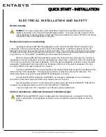
Page 6: ...ent or injury to the user or to others in the vicinity DANGER describes an operating condition or user action that will immediately damage the equipment and or be extremely dangerous or life threatening to the user or to others in the vicinity RIGGING AND ELECTRICAL SAFETY DANGER The loudspeakers described in this manual are designed and intended to be flown or suspended using a variety of rigging...

Page 7: ...aler and the factory will try to help in any way they can but it is the responsibility of the party receiving the shipment to file the damage claim It s always a good idea to retain the carton and packing materials indefinitely if possible in the event that the unit may need to be returned to your dealer or distributor for repair in the future WHAT S IN THE BOX Each shipping carton contains the fo...

Page 8: ...nity ENTASYS Installation Operation Manual Page 8 QUICK START FEATURES ENTASYS FEATURES Figure 1 below on this page and Table 1 on the following page identify basic ENTASYS features Figure 1 ENTASYS Features ...

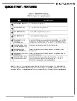
Page 9: ...COMPATIBLE LOCKING CCONNECTOR 4 pole NL4MP type jack wired in parallel with other input and thru connectors Accepts NL4FC type connectors for signal input to loudspeaker Use terminals 1 Terminals 2 are not connected DUAL BANANA JACK INPUT CONNECTOR Standard dual banana jack for input to loudspeaker BARRIER STRIP INPUT TERMINALS Nuts on threaded posts to accept bare wire or lugs for input to loudsp...

Page 10: ...oudspeaker using the supplied Banana Plug Jumper Insert this jumper into the Banana Thru connector on the top of the lower loudspeaker When the upper loudspeaker is placed on top of the lower loudspeaker the Banana Plug Jumper will fit into the Banana Input Jack of the upper loudspeaker No other connecting cable for the upper loudspeaker is required The top most ENTASYS in an array should have the...

Page 11: ...g should be used for each stacked array WARNING It is essential that all installation work involving the suspension of these loudspeaker products be performed by competent knowledgeable persons who understand safe rigging practices Severe injury and or loss of life may occur if these products are improperly installed WARNING The M4 set screws that secure the Mounting Bracket must be fully tightene...

Page 12: ...SYS loudspeakers offer numerous features and technology that provide unprecedented sonic quality and installation flexibility Some of these include Unique three way full range line array column with advanced passive crossover technology Patent pending Compact Ribbon Emulator high frequency elements provide narrow well behaved vertical directivity control Midrange and high frequency drivers use sea...

Page 13: ...employ high frequency drivers use DYNA TECH Advantages of Community s DYNA TECH Circuitry There are numerous advantages to this type of multi stage protection circuitry The trip point is preset to engage at exactly the same time on all loudspeakers that are powered from the same amplifier channel The initial stages of DYNA TECH protection circuitry do not rely on and are not affected by heat build...

Page 14: ... also be used if desired but is not required to deliver exceptional sound quality Each ENTASYS loudspeaker has its own internal passive crossover to provide the required filtering An external high pass filter is recommended to allow ENTASYS to reach its maximum performance potential All ENTASYS systems are available from the factory in elegant black or white finishes They can also be ordered in cu...

Page 15: ...columns to the array This can be much more cost effective than adding full range columns when the maximum required SPL in the higher frequency region can be achieved in the audience area with a single full range column Part of the performance of ENTASYS is due to its internal passive crossover This uses high order slopes passive equalization and proprietary techniques to integrate all sixty six dr...

Page 16: ...Community ENTASYS Installation Operation Manual Page 16 MODELS EASE SpeakerLab Figure 2 Vertical Directivity Map of One ENTASYS Full Range Column at 50 meters EASE SpeakerLab ...

Page 17: ...eaker in order to attach other brackets or fly kits to it This is most easily accomplished by either laying the ENTASYS loudspeaker on its side or placing it upside down on a level surface There are eight set screws four on each side of the rear of the enclosure that secure this bracket to the enclosure Once these are suffi ciently loosened the Mounting Bracket may be slid down parallel to the enc...

Page 18: ...e to be placed on the Mounting Bracket A 12 screw is the largest size screw head that will fit flush in the countersink and not interfere with placing the ENTASYS enclosure on the Mounting Bracket 4 Use a screw in all sixteen 16 of the hole locations in the T Mounting Bracket as shown in Figure 7 Fail ure to do this may lead to an unsafe mounting 5 Once the T Mounting Bracket has been securely mou...

Page 19: ...WARNING The screws used and wall material onto which the Mounting Bracket is attached must be capable of supporting the load of the ENTASYS loudspeaker to be mounted It is the responsibility of the installer to verify these items Figure 7 Wall Mounted T Mounting Bracket ...

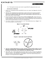
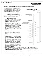
Page 20: ... that the nuts and bolts are securely tightened Failure to do this may result in unsafe construction of the array 3 If more than two ENTASYS columns are to be connected together repeat Step 2 as necessary for connecting up to five T Mounting Brackets together 4 Stack the ENTASYS columns together in the re quired order for the array to be constructed This may be done vertically by stacking them on ...

Page 21: ...Coupler Bracket on Page 20 2 Securely fasten eight of the M6 bolts and nuts to the T Mounting Bracket using four in the upper most por tion of the T Mounting Bracket and four in the lower most portion of the T Mounting Bracket This will yield eight mounting studs for the Pan Brackets Do this before attaching either of the Pan Brackets or the washers to the T Mounting Bracket 3 Attach one of the Pa...

Page 22: ...ar Mounting Brackets using the appropriate number of ENTASYS Coupler Brackets and perform Step 6 by attaching the entire T Bar Mounting Bracket and Pan Bracket assembly to the wall Slide the individ ual ENTASYS enclosures down onto the T Bar Mounting Bracket as described in Step 8 starting with the lowermost enclosure Make sure the Bottom Fitting is securely fastened to the bottom of the T Bar Mou...

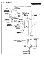
Page 23: ...r five column array the maximum down tilt angle is 5 Instructions for Attachment see Figure 11 1 Remove the T Mounting Bracket from the ENTASYS column to be mounted See Figure 4 for instructions on this removal If multiple columns are to be mounted using a Pan Tilt Bracket see the instruc tions for attaching the columns using the Coupler Bracket on Page 18 2 For a single loudspeaker array securely...

Page 24: ...Community ENTASYS Installation Operation Manual Page 24 ACCESSORIES Figure 11 Pan Tilt Bracket Top Assembly Figure 12 Pan Tilt Bracket Bottom Piece ...

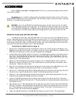
Page 25: ...n all eight of the M4 Set Screws for an enclosure before another ENTA SYS enclosure is placed on top of it Any Dual Banana Plug Jumpers should be placed into position during this step 13 Loosen the M6 screw on the outside portion of the Locking Bar This will allow the array to pivot to point toward the desired location Aim the array and then tighten the M6 screw on the Locking Bar 14 Securely tigh...

Page 26: ...17 7 2 18 7 5 19 7 8 20 8 1 2x Medium 2x Large 21 8 4 22 8 7 23 9 0 24 9 3 3x Medium 2x Large 25 9 6 26 9 9 27 NA 28 NA Two ENTASYS Column Loudspeakers Extension Brackets Holes Angle Small 3 2 1x Medium 1 3 7 2 4 2 3 4 8 4 5 3 1x Large 5 5 8 6 6 3 7 6 8 8 7 4 1x Medium 1x Large 9 7 9 10 8 4 11 8 9 12 9 4 2x Large 13 9 9 14 NA 15 NA 16 NA Table 3 Two ENTASYS Column Down Angles One ENTASYS Column Lo...

Page 27: ...7 2 9 8 3 1 1x Medium 1x Large 9 3 3 10 3 6 11 3 8 12 4 0 2x Large 13 4 2 14 4 4 15 4 7 16 4 9 Table 6 Five ENTASYS Column Down Angles Five ENTASYS Column Loudspeakers Extension Brackets Holes Angle Small 1 1 1x Medium 1 1 2 2 1 4 3 1 6 4 1 7 1x Large 5 1 9 6 2 1 7 2 3 8 2 4 1x Medium 1x Large 9 2 6 10 2 8 11 2 9 12 3 1 2x Large 13 3 3 14 3 5 15 3 6 16 3 8 1x Medium 2x Large 17 4 0 18 4 1 19 4 3 2...

Page 28: ...achment see Figure 14 1 Remove the T Mounting Bracket from the ENTASYS column to be mounted using the Fly Kit See Figure 4 for instructions on this removal If multiple columns are to be mounted using a Fly Kit see the instructions for attaching the columns using the Coupler Bracket in Figure 8 2 Securely fasten the four M6 x 25mm bolts and nuts to the top four holes in the T Mounting Bracket This ...

Page 29: ...e is any interference and properly seat the Fly Bracket Now tighten the two nuts at the bottom of the Fly Bracket 7 Bolt both halves of the Pull Back Bracket to the lower most studs on the T Mounting Bracket using the M6 nuts lock washers and flat washers Securely tighten all four of the nuts The ENTASYS array should now be ready to be suspended Use safe rigging practices when attaching all other ...

Page 30: ...Community ENTASYS Installation Operation Manual Page 30 ACCESSORIES Figure 14 Fly Kit ...

Page 31: ...to mount the transformer directly to a wall as shown in Figure 15 This is the only way to mount the transformer if it is to be placed below an ENTASYS array The transformer may be electrically connected to the ENTASYS array using the barrier strip terminals on the top of the transformer When this mounting is used the included Rubber Plug should be inserted into the bottom dual banana jack recess a...

Page 32: ...ENCY LOUDSPEAKERS The performance goals and design of the ENTASYS loudspeaker systems inherently limits their low frequency extension When frequency response below 200 Hz is required additional low frequency loudspeakers and or subwoofers should be used Community has several high quality low frequency loudspeaker systems that are recommended for use with ENTASYS These include the Versatile Low Fre...

Page 33: ...pe 24 dB oct 48 dB oct 48 dB oct 24 dB oct 24 dB oct 24 dB oct HP Freq 200 Hz 55 Hz 42 Hz 60 Hz 45 Hz 31 Hz LP Filter BU BU BU BU BU LP Slope 24 dB oct 24 dB oct 24 dB oct 24 dB oct 24 dB oct LP Freq 200 Hz 200 Hz 190 Hz 180 Hz 185 Hz Polarity Normal Normal Normal Normal Normal Normal EQ Filter 1 PEQ PEQ PEQ PEQ PEQ PEQ Frequency 350 Hz 58 Hz 45 Hz 70 Hz 80 Hz 35 Hz Bandwidth 0 30 0 20 0 19 0 33 0...

Page 34: ...Community ENTASYS Installation Operation Manual Page 34 ACCESSORIES Figure 18 ENT 750T Transformer Input Label and Connectors ...

Page 35: ...tandard dual banana jack connector The third is a two position barrier strip terminal All of these connectors are wired in parallel Provisions are also made to pass the input signal through the loudspeaker so that it may be easily routed to other loudspeakers This can be accomplished two ways The first is the two position barrier strip thru terminals The other is the recessed dual banana plug conn...

Page 36: ...en using the barrier strip terminals This improves the weather resistant nature of the enclosure The bottom cover has a knock out for a 1 2 inch NPT fitting This allows cables larger than 16 2 SJO to be used or conduit attached to the loudspeaker while sealing the connec tor area from the elements Figure 21 NL4 Type Connection Detail Figure 20 ENTASYS Low Frequency Column Input Panel 16 2 SJO Cabl...

Page 37: ...fers from excessive low frequency excursion High pass filters will help protect the loudspeaker against damage from over excursion and will avoid using amplifier power that s wasted from attempting to reproduce frequencies below the loudspeaker s intended operating range A high pass filter set to at least 200 Hz 24 dB octave should be used Increasing the high pass filter to a higher frequency or g...

Page 38: ... circuitry Use of Limiters Community recommends the use of a limiter to help prevent loudspeaker damage due to sudden transients dropped microphones etc and to prevent amplifier clipping When used for this purpose connect the limiter as the last item in the signal chain before the power amplifier at the input to the power amplifier Set the limiter s threshold high enough so that no limiting occurs...

Page 39: ...1 14 1 16 4 4 1 1 6 2 3 7 1 9 3 11 8 3 9 5 5 14 8 17 0 4 6 1 7 2 4 7 6 9 8 12 0 4 0 5 7 15 1 17 3 5 1 1 8 2 5 8 1 10 3 14 5 5 3 7 5 17 5 19 7 Table 10 Amplifier Sensitivity and Peak Voltage Threshold Settings Full Range Columns Total Rated Impedance ohm Recommended Power watts Required Voltage VRMS Amplifier Rating 8 ohm watts Amplifier Rating 4 ohm watts 1 12 600 85 1 800 3 600 2 6 1 200 85 3 600...

Page 40: ... the Dual Banana Jumper Plug will fit into the Dual Banana Input Jack on the bottom of the second loudspeaker electrically connecting the two loudspeakers in parallel Consult Tables 8 and 9 to determine the rated load of a particular combination of ENTASYS loudspeakers and how to optimally power them Do not attempt to place a low impedance load too many loudspeakers on an amplifier that is not rat...

Page 41: ...gths over 100 feet the wire gauges needed to meet this requirement are usually not practical to use for both physical and cost reasons Therefore 10 AWG is recommended as the most practical gauge for those situations The run length for both conductors has been figured into the total resistance Remember that a lower gauge number means a larger wire size INSTALLATION Run Length Minimum Gauge AWG Tota...

Page 42: ...ts or materials manufactured or supplied by Community shall immediately void all pledges of warranty or surety related in any way to the safe use of those parts and materials WARNING NON COMMUNITY RIGGING HARDWARE Non Community hardware used for rigging an ENTASYS loudspeaker must be certified by the supplier for this use and must be properly rated for safety Important Notes on Rigging Loudspeaker...

Page 43: ...grilles are powder coated steel To paint the grille carefully remove the cloth backing and use paint that is compatible with powder coating to paint the grille Do not paint the cloth Contact Community for replacement grille cloth Apply the grille cloth by using a fine mist of spray adhesive on the grille Do not spray adhesive on the cloth Then attach the cloth by passing it onto the interior surfa...

Page 44: ... modules are attached to the baffle with four M4 screws These screw into taped holes in the aluminum baffle There are no nuts to have to hold or catch inside the enclosure Shorter screws are used with some of the smaller spacers These will need to be replaced with the included longer 60 mm screws when the larger 34 2 mm spacer is used INSTALLATION 34 2 mm Spacer 12 31 4 mm Spacer 2 23 2 mm Spacer ...

Page 45: ...45 Increasing line array length compared to wavelength results in a narrower more well defined radiation lobe For a very small opening aperture beamwidth the line length may need to be four times as long as the wavelength to be controlled Table 12 shows the relationship between frequency wavelength the size of single and multiple column ENTASYS arrays and the directivity control expected When the ...

Page 46: ...d ceilings or other obstructions Ideally put all loudspeakers in a central location central cluster design or use a distributed system design Choose power amplifiers large enough to achieve the needed SPL in the venue with enough headroom to avoid clipping Use a limiter and high pass filter to protect the loudspeakers Follow proper wiring design and adjust gains and levels to achieve the best sign...

Page 47: ...FULL RANGE COLUMNS When additional directivity control is required a second ENTASYS full range column may be added to an array This will yield not only greater directivity control in the low frequency region but also a more narrow beamwidth in the high frequency region This results from the increased line length for all frequencies For this configuration the best results will be achieved for most ...

Page 48: ... focused main lobe at these lower frequencies Figure 28 shows an SPL map for a single ENTASYS full range column for the one octave band centered at 500 Hz Figure 29 shows the same map but with a single low frequency column placed on top of the full range column A comparison of these SPL maps shows the increased directivity more narrow beamwidth of the array using the low frequency and full range c...

Page 49: ...line source The line source inherently has a height associated with it at its origin while a point source does not This fundamental difference can greatly alter the way a line array can be used to cover an area with sound As more columns are added to an array the line length gets longer This results in the narrowing of the vertical beamwidth of the array At the same time the coverage of the array ...

Page 50: ...mparison of the sound radiation easier Notice how the height of the main radiation lobe increases at a distance of say 60 70 feet from the array as more columns are added This occurs even though the coverage angle is decreasing Figure 30 One Full Range Column 2 kHz EASE Focus Figure 31 Three Full Range Columns 2 kHz EASE Focus Figure 32 Six Full Range Columns 2 kHz EASE Focus Lobe Height approxima...

Page 51: ...tors LF Six 3 5 drivers with optimized spacing allows extension of the narrow vertical beamwidth into the lower frequencies MF HF Driver Configuration Straight Curved or Asymmetric Curved Straight Input Connections Top 1 Dual Banana Plug male Bottom 1 NL4 locking connector 1 Dual Banana Jack female 2 Terminal Strip Top 1 Dual Banana Plug male Bottom 1 NL4 locking connector 1 Dual Banana Jack femal...

Page 52: ...or 1FR 2LF or 2FR or 2FR 1LF 200 Hz 15 kHz 0 5 2 0dB 3FR 200 Hz 7 kHz 1 0 1 0dB 3FR 200 Hz 15 kHz 1 0 3 0dB ENTASYS 750 W Autoformer Frequency Response See Chart Below Insertion Loss 0 5 dB Low Frequency Limit at Maximum Input 100 Hz Recommended HP Filter 200 Hz 24 dB octave Input Connections Top Barrier Strip Terminals Bottom 1 Dual Banana Jack female Enclosure One piece aluminum extrusion with m...

Page 53: ...Community ENTASYS Installation Operation Manual Page 53 DIMENSIONS Figure 33 ENTASYS Full Range Column Dimensions ...

Page 54: ...Community ENTASYS Installation Operation Manual Page 54 DIMENSIONS Figure 34 ENTASYS Low Frequency Column Dimensions ...

Page 55: ...Community ENTASYS Installation Operation Manual Page 55 DIMENSIONS Figure 35 ENT 750T 750 watt Autoformer Dimensions ...

Page 56: ...odifica tion improper handling installation or repairs made without factory authorization or by anyone other than authorized Community Field Service Stations This warranty is void if the serial number has been defaced altered or removed Products covered by this warranty will be repaired or replaced at the option of Community without charge for materi als or labor provided all the terms of this war...

Page 57: ...all not be liable for any consequential or incidental damages including without limitation injury to persons property or loss of use Some states do not allow the exclusion or limitations of consequential or incidental damages so the above limitations and exclusions may not apply This Community warranty is not extended by the length of time which an owner is deprived of the use of the product Repai...

Page 58: ...Community ENTASYS Installation Operation Manual Page 58 NOTES ...

Page 59: ...Community ENTASYS Installation Operation Manual Page 59 NOTES ...

Page 60: ...onal Loudspeakers 333 East Fifth Street Chester PA 19013 4511 USA TEL 1 610 876 3400 FAX 1 610 874 0190 www communitypro com 2009 All Rights Reserved ENTASYS OM 20090709 ENTASYS HIGH PERFORMANCE COLUMN LINE ARRAY SYSTEM ...

Reviews: