Community ENTASYS Installation/Operation Manual — Page 21
ACCESSORIES
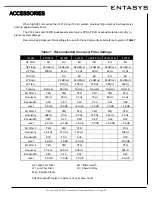
Refer to
Figure 1 and Table 1 on Pages 8 and 9
if there is any uncertainty identifying these parts and
where they are located.
Assembly Tip:
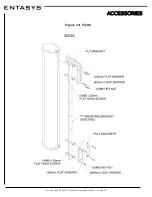
Use a C-clamp of locking pliers (vise-grips) to align the ends for the two “T” Mounting
Brackets before bolting them to the Coupler Bracket. Leave the clamp in place until all of the screws have been
tightened. This will assure proper alignment.
WARNING:
Up to four (4) ENTASYS Coupler Brackets may be used to connect up to five (5) ENTA-
SYS loudspeakers together into a single array. Do not attempt to construct a single array or more than
five (5) ENTASYS loudspeakers. Attempting to do so will exceed the Working Load Limit of the bracket
and could result in the failure of the bracket and potentially result in severe injury and/or loss of life.
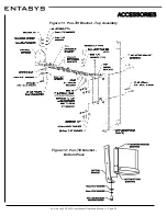
ENTASYS Pan Bracket: ENT-PB, ENT-PBW
The ENTASYS Pan Bracket, designated ENT-PB, can be used to mount up to five ENTASYS columns
flush on a wall while providing a means to rotate the entire array up to 80° (5° - 85° aiming angles) about a verti-
cal axis. The Pan Brackets may be installed on a wall in either a left-hand or right-hand orientation as required
for the desired aiming of the array. The Pan Bracket consists of two curved metal brackets and all of the hard-
ware required to attach these brackets to the “T” Mounting Bracket.
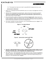
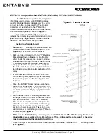
Instructions for Attachment (see Figure 9)
1. Remove the “T” Mounting Bracket from the ENTASYS column to be mounted using the Pan Bracket. See
Figure 4
for instructions on this removal. If multiple columns are to be mounted using a Pan Bracket see the
instructions for attaching the columns using the Coupler Bracket on
Page 20
.
2. Securely fasten eight of the M6 bolts and nuts to the “T” Mounting Bracket using four in the upper most por-
tion of the “T” Mounting Bracket and four in the lower most portion of the “T” Mounting Bracket. This will
yield eight mounting studs for the Pan Brackets. Do this before attaching either of the Pan Brackets or the
washers to the “T” Mounting Bracket.
3. Attach one of the Pan Brackets to the upper most studs on the “T” Mounting Bracket and the other Pan
Bracket to the lower most studs on the “T” Mounting Bracket using the flat washers, lock washers, and re-
maining nuts. Tighten the nuts securely.
4. Place the “T” Mounting Bracket and Pan Bracket assembly on the wall where the ENTASYS array is to be
installed. Mark the positions on the wall where the holes in the Pan Bracket are located.
5. Remove the “T” Mounting Bracket and Pan Bracket assembly from the wall and properly prepare the wall to
accept the correct type of bolts with which to attach the Pan Bracket assembly to the wall.
6. Attach the “T” Mounting Bracket and Pan Bracket assembly to the wall using the proper bolts for the wall
material and the weight of the ENTASYS array to be mounted.
7. Loosen the eight M6 nuts between the Pan Bracket and the wall (not the nuts between the “T” Mounting
Bracket and the Pan Bracket) and rotate the “T” Mounting Bracket to its approximate desired aiming location
and retighten the nuts.
8. Align the tabs on the “T” Mounting Bracket with the larger opening in the slot on the back of the ENTASYS
enclosure. Insert the “T” Mounting Bracket into the slot in the enclosure and slide the enclosure down onto
the “T” Mounting Bracket until it is resting on the Bottom Fitting. This is done in a similar manner as reat-
taching a single “T” Mounting Bracket (see
Figure 4
).
9. Tighten the eight M4 Set Screws on the ENTASYS enclosure to secure it to the “T” Mounting Bracket.


