


ComNav P4 Remotes Installation & Operation
Introduction
Document PN 29010102 V1r1
- 9 -
Overview of the TS4 Remote
The TS4 Remote is designed to work with ComNav’ s P4 Autopilot System.
The TS4 Remote allows the vessel operator to control the P4 Autopilot’s steering
functions from a workstation, flying bridge, on the side or stern decks, or any other
remote location on the vessel.
Features included in the TS4 Remote:
•
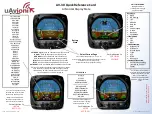
Backlit graphical LCD display shows important system information, with easy selection
of display brightness and day-night display mode.
•
Selection of’
STANDBY
,
AUTO
, and
NAV
modes are done using the Mode button
(also supports
WORK
mode when in
AUTO
mode)
•
Handheld operation, with built-in slots for “hang-up posts” on the back side
•
Fully watertight case, made of high-impact material with excellent resistance to most
chemicals, a cable strain relief and button/switch & Tiller knob seals
•
NMEA 2000 installation
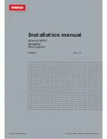
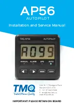
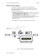
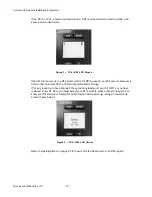
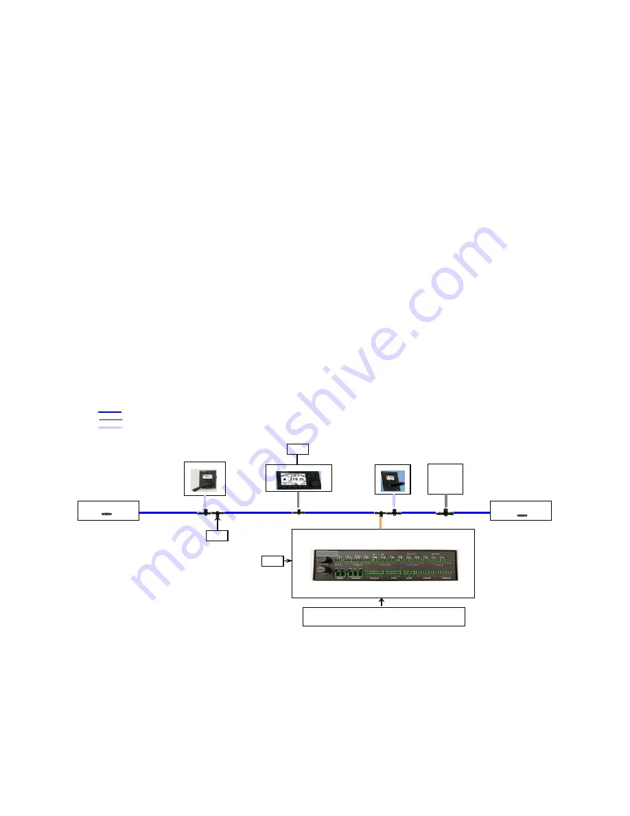
The block diagram below shows how the TS4 Remote is used in a P4 system:
NMEA2000 Terminator
(Female), PN31810015
P4
SPU,
PN20140001
P4
Control Head
TS
4
Remote
NF
4
Remote
NMEA 2000(N2K) Connection - 6m drop cable, Male & Female (PN31110052)
NMEA2000 Terminator
(Male), PN31810016
NMEA 2000(N2K) Connection - Trunk (Backbone) cable
12-24V
Battery
Block Diagram of the
P4
System
12-24V
Battery
12-24V
Battery
N2K devices
(Compass,
Plotter etc.,)
Connections for :
All Analog devices such as
Fluxgate & Magnetic Compasses, Rotary Rudder
Follower, Drives & Motors.
All NMEA devices such as Compasses & Navigation plotters
N2K
Pigtail to M ale C ab le,
1 m, PN61110063
2 m, Head Power Cable,
PN61110072
N2K
T -connector,
PN31810008
SiTex SP 3 8
NMEA 2000(N2K) Connection - 6m cable, Pigtail & Male (PN31110073)
Figure 1 – P Series Autopilot System (partial diagram)
Summary of Contents for P4 Remotes Series
Page 2: ......
Page 8: ...ComNav P4 Remotes Installation Operation Document PN 29010102 V1r1 6...
Page 9: ...ComNav P4 Remotes Installation Operation Document PN 29010102 V1r1 7 Introduction...
Page 10: ...ComNav P4 Remotes Installation Operation Document PN 29010102 V1r1 8...
Page 14: ...ComNav P4 Remotes Installation Operation Document PN 29010102 V1r1 12...
Page 15: ...ComNav P4 Remotes Installation Operation Document PN 29010102 V1r1 13 Installation...
Page 16: ...ComNav P4 Remotes Installation Operation Document PN 29010102 V1r1 14...
Page 19: ...ComNav P4 Remotes Installation Operation Document PN 29010102 V1r1 17 Operation...
Page 20: ...ComNav P4 Remotes Installation Operation Document PN 29010102 V1r1 18...
Page 28: ...ComNav P4 Remotes Installation Operation Operation Document PN 29010102 V1r1 26...
Page 29: ...ComNav P4 Remotes Installation Operation Document PN 29010102 V1r1 27 Appendices...
Page 30: ...ComNav P4 Remotes Installation Operation Document PN 29010102 V1r1 28...
Page 32: ...ComNav P4 Remotes Installation Operation Appendices Document PN 29010102 V1r1 30...
Page 33: ...ComNav P4 Remotes Installation Operation Appendices Document PN 29010102 V1r1 31 Index...
Page 34: ...ComNav P4 Remotes Installation Operation Appendices Document PN 29010102 V1r1 32...
Page 36: ...ComNav P4 Remotes Installation Operation Document PN 29010102 V1r1 34...
Page 37: ...ComNav P4 Remotes Installation Operation Document PN 29010102 V1r1 35 User Notes...
Page 38: ...ComNav P4 Remotes Installation Operation User Notes Document PN 29010102 V1r1 36...
Page 39: ...ComNav P4 Remotes Installation Operation User Notes Document PN 29010102 V1r1 37 User Notes...
Page 40: ...ComNav P4 Remotes Installation Operation User Notes Document PN 29010102 V1r1 38...