background image

ComNav P4 Remotes Installation & Operation 

Document PN 29010102 V1r1


- 15 - 

Installation 

Technical Requirements 

The following are the basic technical requirements that should be met before installation of 
the TS4 Remote on your vessel. 

For information regarding the installation of the complete P4 Autopilot 
System, consult your P4 Installation & Operation Manual. 

Caution Warning 

Please refer to the 

Warranty Information

 document that accompanies your 

P Series manual before proceeding with installation of the 

 Remotes


Hazard warning! 

CAUTION! 

Extreme  caution  is  advised  when  using  tools  powered  by  alternating 
current  (AC)  from  main  AC  supply  circuits,  regardless  of  whether  the 
supply  circuits  are  “indoor”,  “outdoor”,  “marine”  or  “industrial”  rated.  
Water, especially sea water, is an 

EXCELLENT

 conductor of electricity, 

and  can  complete  a  path  to  AC  Ground  through  a  person’s  body, 
causing injury or death, if a tool malfunctions or short-circuits. 

 Battery powered tools are 

STRONGLY

 recommended 


If  AC  tools  are  used,  they 

MUST

  be  plugged  into  a  circuit  that  is 

adequately  protected  against  Ground  Faults  and  other  safety  hazards, 
in accordance with local electrical codes. 

 
Electrical Connections 

A P4 remote (TS4 or NF4) comes with a 6-meter cable with a male 5-pin micro NMEA 2000 
connector. Each unit is also shipped with a T-connector. Insert the T connector to a 
convenient location in your system, taking into the consideration to make a balanced 
installation for the whole system. 


Network Connection in a P4 system 

An out-of-box P4 remote (TS4 or NF4) will automatically connect to a P4 SPU it first sees 
after power up. If you have a P4SPU, and you have never made an installation change to the 
P4 SPU from its factory default, once you power up your P4 remote, the P4 remote is ready 
to take command and steer your boat as described in the Operation section. 

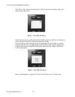
P4 remote is an accessory. It can only be used to operate the autopilot when the autopilot 
has started up and in normal operation modes. Normal operation modes for P4 SPU are 
Standby mode, Auto mode, Power Steer mode and Nav mode.  

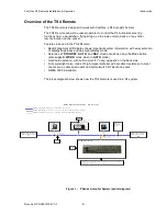
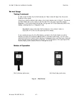
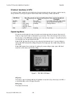
In normal operation mode, a P4 remote displays a screen like those in Figure 3. 


Summary of Contents for P4 Remotes Series

Page 1: ...TS4 Full Follow Up Remote NF4 Non Follow up Joystick Remote Installation Operation Manual P4 Remotes for P4 Autopilot Systems PN 29010102 COMPLIES WITH CE REGULATIONS...

Page 2: ......

Page 3: ...formation of that system Operator s Warning The P4 Autopilot System with or without the Remotes will steer your vessel However it is only an aid to navigation Its performance can be affected by many f...

Page 4: ...ComNav P4 Remotes Installation Operation Welcome Document PN 29010102 V1r1 2 Document History Revision Date Description 1R0 10 August 2018 first release...

Page 5: ...hrases Terms 10 Manual Format 11 Installation 13 Technical Requirements 15 Caution Warning 15 Electrical Connections 15 Network Connection in a P4 System 15 Operation 17 User Interface 19 Display Cont...

Page 6: ...ComNav Remote Installation Operation Table of Contents Document PN 29010102 V1r1 4 Appendices 27 Multi SPU Installation 29 Care Maintenance 29 Specifications 29 Index 31 User Notes 37...

Page 7: ...PN 29010102 V1r1 5 List of Figures Figure 1 P Series Autopilot System partial diagram 9 Figure 2 Mode Buttons 21 Figure 3 TS4 NF4 LCD Screen 16 24 25 List of Tables Document History 2 User Interface 1...

Page 8: ...ComNav P4 Remotes Installation Operation Document PN 29010102 V1r1 6...

Page 9: ...ComNav P4 Remotes Installation Operation Document PN 29010102 V1r1 7 Introduction...

Page 10: ...ComNav P4 Remotes Installation Operation Document PN 29010102 V1r1 8...

Page 11: ...ade of high impact material with excellent resistance to most chemicals a cable strain relief and button switch Tiller knob seals NMEA 2000 installation The block diagram below shows how the TS4 Remot...

Page 12: ...on TS4 Remote buttons and controls are placed in uppercase lettering Example the MODE button System Component Specific System Components are capitalized Example The Control Head LCD Display Text that...

Page 13: ...n Adobe Portable Document Format pdf and so may be viewed printed with Adobe Reader or compatible pdf format viewers When printing this manual with Reader you should select duplex printing or the equi...

Page 14: ...ComNav P4 Remotes Installation Operation Document PN 29010102 V1r1 12...

Page 15: ...ComNav P4 Remotes Installation Operation Document PN 29010102 V1r1 13 Installation...

Page 16: ...ComNav P4 Remotes Installation Operation Document PN 29010102 V1r1 14...

Page 17: ...ded If AC tools are used they MUST be plugged into a circuit that is adequately protected against Ground Faults and other safety hazards in accordance with local electrical codes Electrical Connection...

Page 18: ...our P4 remote however is fixed to that particular SPU and will not automatically change If for any reason you have changed the network installation of your P4 SPU or you have replaced a new P4 SPU you...

Page 19: ...ComNav P4 Remotes Installation Operation Document PN 29010102 V1r1 17 Operation...

Page 20: ...ComNav P4 Remotes Installation Operation Document PN 29010102 V1r1 18...

Page 21: ...tiate Mode selection menu Click Mode selection menu REMOTE is in command Move to the next available mode Click Configuration menu Root menu Move to the previous menu line Click Configuration menu Edit...

Page 22: ...efers to the brightness of the LCD backlighting There are 8 levels available a level of 1 is the minimum level of backlight while 8 is the brightest Day Night mode The high brightness may be a safety...

Page 23: ...portion of the display indicating that it is in Repeater mode Important Always remember that the Remote is in command unless a large letter R is shown in the upper right of the display To take command...

Page 24: ...e Auto power steer nav Nav Power steer auto TILLER Mode When your P4 remote is model TS4 the Power steer mode of P4 system becomes TILLER mode The autopilot will move the rudder to follow the position...

Page 25: ...in WORK mode for most vessel types Refer to the appropriate section in the P4 Installation Operation manual for details on these modes Course Recall Some time when you are in Auto mode you want to tem...

Page 26: ...for easy connection and simple operation However there are still times you may need to make a few twists to your remote This is done through the root menu Double click on the CMD button will bring up...

Page 27: ...ct the P4 remote to a specific SPU you must first POWER OFF the SPU you don t want before you press LITE to link the SPU you want Numbers behind P4SPU 030 are the last 3 digits of the serial number of...

Page 28: ...ComNav P4 Remotes Installation Operation Operation Document PN 29010102 V1r1 26...

Page 29: ...ComNav P4 Remotes Installation Operation Document PN 29010102 V1r1 27 Appendices...

Page 30: ...ComNav P4 Remotes Installation Operation Document PN 29010102 V1r1 28...

Page 31: ...the group number has changed the Remote will automatically delete SPU information it has already pick up and scan the network all over again Care Maintenance There are no user serviceable parts or adj...

Page 32: ...ComNav P4 Remotes Installation Operation Appendices Document PN 29010102 V1r1 30...

Page 33: ...ComNav P4 Remotes Installation Operation Appendices Document PN 29010102 V1r1 31 Index...

Page 34: ...ComNav P4 Remotes Installation Operation Appendices Document PN 29010102 V1r1 32...

Page 35: ...tes Installation Operation Index Document PN 29010102 V1r1 33 Index Double press 10 Installation 13 Maintain 10 Momentary press 10 Power Supply 15 Press 10 Press and hold 10 Technical Requirements 15...

Page 36: ...ComNav P4 Remotes Installation Operation Document PN 29010102 V1r1 34...

Page 37: ...ComNav P4 Remotes Installation Operation Document PN 29010102 V1r1 35 User Notes...

Page 38: ...ComNav P4 Remotes Installation Operation User Notes Document PN 29010102 V1r1 36...

Page 39: ...ComNav P4 Remotes Installation Operation User Notes Document PN 29010102 V1r1 37 User Notes...

Page 40: ...ComNav P4 Remotes Installation Operation User Notes Document PN 29010102 V1r1 38...

Reviews: