background image

SinoGNSS

R

  T300 User Guide 


33 


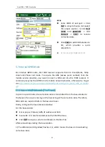
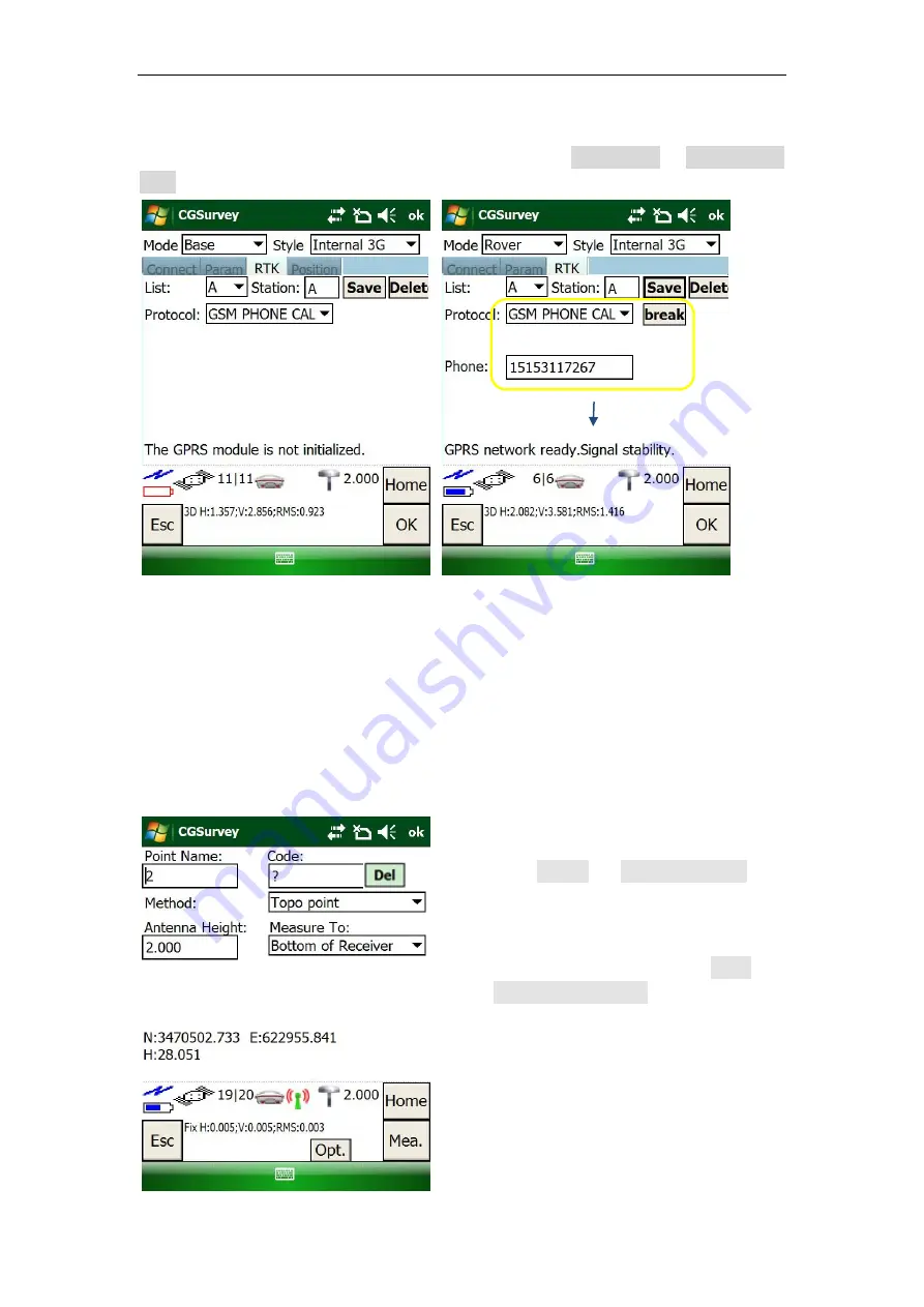
5.7.3 Phone call mode 

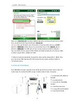
Two SIM cards are required in phone call mode,  select 

Internal 3G

 -> 

GSM PHONE 

CALL

 Protocol for the Base and Rover, settings are shown below: 


6 Basic Survey Functions 

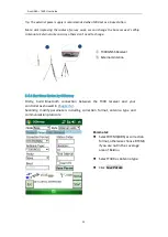
This  section  describes  the  basic  survey  functions  of  CGSruvey,  including  point 
measurement,  Topo  survey,  staking,  site  calibration,  import  and  export  measured 
points.


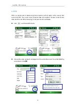
6.1 Measuring Points 


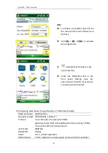
Click 

Survey

  -> 

Measure  Points

then you can measure  points. 


Enter point name, antenna height 
and survey mode, then click 

Mea. 

(Or Press F2 button)

 to start your 

survey. The point coordinates will 
be saved in your controller. 


Phone number of the Base 

Summary of Contents for SinoGNSS T300

Page 1: ...SinoGNSS R T300 User Guide T300 GNSS Receiver User Guide Version 1 05 October 2017...

Page 2: ...peration Copyright Notice This is the V1 05 October 2017 revision of the T300 GNSS Receiver User Guide It cannot be copied or translated into any language without the written permission of ComNav Tech...

Page 3: ...The receiver can withstand the rough treatment that typically occurs in the field However the receiver is high precision electronic equipment and should be treated with reasonable care Warning and Cau...

Page 4: ...Raw Data Download 14 4 3 2 Convert toRINEX 15 4 3 3 Memory Management 17 5 Real Time Kinematic Survey RTK 18 5 1 Installation of CGSurvey Software 18 5 2 Start a New Project 19 5 3 Bluetooth connecti...

Page 5: ...SinoGNSS R T300 User Guide 2 7 Specifications 42 Appendix A 7 Pin Lemo definition 43 Appendix B Setting up of PDL 43 Appendix C Connect your controller to the Internet 46...

Page 6: ...Ultra small and super light Size W H 15 8cm 7 5cm Weight 0 95kg including 2 batteries 256 channels of simultaneously tracked satellitesignals Increased measurement traceability with SinoGNSS R QUAN a...

Page 7: ...0 User Guide 4 Item Picture 2 Kits T300 Receivers 1 GNSS Connector 2 7 pin Lemo to RS232 Cable 2 7 pin Lemo to USB Cable External Power Cable 2 Whip Antenna UHF 1 2m Range Pole with yellow bag 4 Lithi...

Page 8: ...Data Cable of Controller Controller Charger and Cable Controller Bracket Optional accessories Double Bubbles Tribrach with High Adapter 1 30cm Extension bar 1 3 2 Optional Datalink kit This kit is nec...

Page 9: ...T300 Datalink cable Configuration cable Datalink Antenna External Power Cable Aluminum Bracket Extension Bar 1 3 3 Transport Cases Standard transport Case is designed for containing Basic supply kit o...

Page 10: ...SinoGNSS R T300 User Guide 7 Base Rover The optional choice is provided to have capacity of two kits of T300 receivers...

Page 11: ...temperature 45 C to 85 C Out of corrosive fluids and gases With a clear view of sky 2 2 Front panel Receiver front panel contains five indicator light emitting diodes LEDs Power button and record butt...

Page 12: ...include but are not limited to discoloration warping and leaking battery fluid Do not expose the battery to fire high temperature or direct sunlight Do not immerse the battery in water Do not use or...

Page 13: ...n battery A damaged battery can cause an explosion or fire and can result in personal injury and or property damage 2 4 2 External PowerSupply The receiver is connected to an external power supply thr...

Page 14: ...until all LEDs off Record button Switch to static mode Long press the record button for about 2 seconds release immediately when hearing beep from receiver Switch to RTK mode press the button until R...

Page 15: ...off Power LEDs Power supply 1 Two power LEDs are on if using the external power supply 2 Only power LED of working battery will be on if using the internal battery Low battery 1 Power LED will flash...

Page 16: ...he receiver and raw observation data downloading 2 with 7 pin Lemo to RS232 cable you can connect T300 receiver with external power or firmware upgrade 4 Click Config to configure the receiver Sample...

Page 17: ...g to other observation site To quickly post process static observation raw data write down the station name receiver SN antenna height start and end time for each observation site 4 3 Static data mana...

Page 18: ...observation data in download path Click Delete to remove raw data from the receiver 4 3 2 Convert toRINEX After downloading raw observation data to your PC go to to convert from ComNav binary format c...

Page 19: ...t If you cannot find T300 antenna 1 input the value of R0 horizontal offset from measurement mark to phase center and h0 vertical offset from measurement mark to phase center R0 is 0 079m and h0 is 0...

Page 20: ...al memory runs out the differential LED and data logging LED will flash simultaneously with 2 second interval In this case you need to format the internal memory before starting another static survey...

Page 21: ...software installation start a new project receiver connection and RTK working modes radio CORSandGPRS 5 1 Installation of CGSurvey Software Install Microsoft Windows Mobile Device Center or Microsoft...

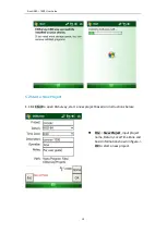
Page 22: ...19 5 2 Start a New Project 1 Click Start to open CGSurvey start a new project based on instructions below File New Project input project name Datum Local Time Zone and basic information shown in figur...

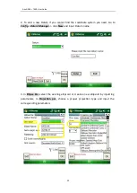
Page 23: ...e coordinate system you need Go to Config Datum Manager click New and input Datum name 3 In Ellipse Par select the existing ellipsoid or create a new ellipsoid by inputting parameters In Projection pa...

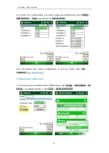
Page 24: ...ig Administrator Login user password admin admin 5 For Horizontal and Vertical Adjustment it will be shown after Site Calibration see chapter 6 5 1 5 3 Bluetooth connection 1 To connect your controlle...

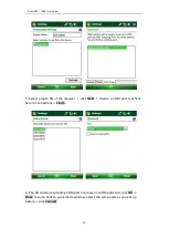
Page 25: ...ce select corresponding SN number of the receiver click Next Tip Make sure T300 receiver is powered on before searching devices 3 Input the passcode 0000 and click Next Advanced 4 Check Serial Port cl...

Page 26: ...N of the receiver click Next choose a COM port uncheck Secure Connection Finish 6 The SN and corresponding COM port are shown in COM ports tab click OK Done to come back to work mode window Select the...

Page 27: ...M8 and COM9 as Bluetooth port while our R200 controller support COM7 COM8 and COM9 7 After connected successfully the position status will be showed H V RMS Then you can set up T300 receiver with the...

Page 28: ...change 5 4 1 Start Base Station by CGSurvey Firstly build Bluetooth connection between the T300 receiver and your controller as showed in Chapter5 3 Secondly modify parameters including correction fo...

Page 29: ...se station Check Fix Base and click Start to complete the configuration RTK Select Transparent as Protocol transmitting receiving mode Set proper frequency and Power Tip If you use external antenna in...

Page 30: ...y Connect your controller to T300 receiver based on Chapter 5 3 and allocate the Rover another COM port that different from the Base Click OK to save configuration Check the differential LED in the fr...

Page 31: ...EOT and southprotocol Airlink rate 9600 bps Bandwidth 25kbps Power 0 5 1 2 Watt adjustable Work distance 1 5km depends on powersupply and environment condition RTK To achieve a successful data link se...

Page 32: ...0 receiver and external radio 2 See Appendix B for the operating information of PDL Warning 1 You MUST connect PDL to external antenna firstly and supply power next otherwise the PDL will have a risk...

Page 33: ...r GPRS and run CGSurvey software 2 Build Bluetooth connection as showed in chapter 5 3 Click Config Work Mode select Rover and PDA Net 3 Change the parameters including Base index antenna type and hei...

Page 34: ...n to the Server then rovers can log on the Server to get the correction data Therefore SIM cards are required both in the base and rover Firstly configure the base station as below For the base statio...

Page 35: ...PN address and Source as the base click OK when GPRS network ready 5 7 2 Internal 3G Ntrip client mode For Ntrip client mode rover station acquires correction data from Ntrip CORS server Do configurat...

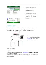
Page 36: ...s section describes the basic survey functions of CGSruvey including point measurement Topo survey staking site calibration import and export measured points 6 1 Measuring Points Click Survey Measure...

Page 37: ...at cannot do RTK The rover survey dynamic data and another receiver record static data and then do PPK processing in Compass Solution software Click and choose PPK mode Choose file name and path and a...

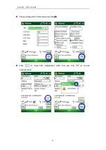
Page 38: ...SinoGNSS R T300 User Guide 35 Check configuration information and click OK Click to make PPK initialization After that just click as normal measurement...

Page 39: ...nuous Topo to measure points continuously It provides 4 different Methods to measure points Fix Time Fix Distance Time and Distance Time or Distance Export data to PC and using Compass Solution softwa...

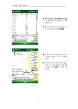
Page 40: ...e out points to the points list Then select the point name you want to stake and click Stake It shows the navigation from the current position to the target point It will alarm you if the receiver get...

Page 41: ...Import all known points c1 c2 c3 into controller see chapter 6 7 2 Start base station successfully measure all the known points by the rover a1 a2 a3 The function of COGO in CGSurvey includes Compute...

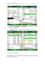
Page 42: ...osition of base station in the same project The following example shows that reset point 2 based on point 1 known point 4 After adding all the points in the list click Cal button the software will cal...

Page 43: ...nager double click on the point you need to reset Point 2 2 Click Reset Grid to add the known point Point 1 OK to finish Grid Reset 6 7 Export Points toyourPC The measured data can be exported directl...

Page 44: ...ontroller root directory Then open CGSurvey on your controller click File Import Grid point select proper file format select the file in root directory Import OK Go to File Export points select the co...

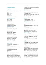
Page 45: ...le with Windows OS and Android Data Format Correction data I O RTCM 2 X 3 X CMR GPS only CMR GPS only Position data output ASCII NMEA 0183 GSV RMC HDT VHD GGA GSA ZDA VTG GST PJK PTNL ComNav Binary up...

Page 46: ...ternal radio mode connect all devices through provided cables according to the figure below 7 pin Lemo Description 1 Signal GND 2 GND 3 TX data out TXD 4 NONE 5 NONE 6 Power In 7 Serial data in RXD 1...

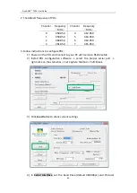
Page 47: ...461 050 7 465 050 3 Follow instructions to configure PDL 1 Power on the PDL and Connect to your PC with Lemo to RS232 cable 2 Install PDL configuration software select the proper serial port right cli...

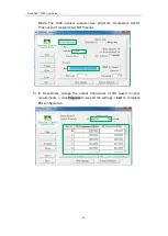
Page 48: ...receiver supports two protocols Transparent w EOT Timeout and Transparent w EOT Timeout 5 In Frequencies change the output frequencies of PDL based on your requirements click Program to save all the...

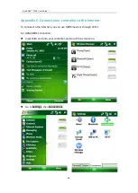
Page 49: ...ppendix C Connect your controller to the Internet To connect to the internet you can use GPRS mode or through WI FI For GSM GPRS connection Insert SIM card into your controller and turn Phone mode on...

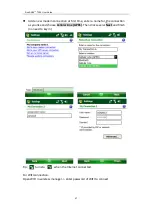
Page 50: ...irst time enter a name for the connection as you like and choose Cellular Line GPRS Then click several Next and finish no need to key in Tip turns to when the Internet connected For WIFI connection Op...

Page 51: ...figurable 2 Bluetooth Module Frequency Range 2 402Ghz 2 480Ghz RF Power Max 4dBm Band Width 2Mhz 3 3G Module TX Output Power Max Band Power Class GSM900 4 2W DCS1800 1 1W EDGE 900Mhz E2 0 5W EDGE 1800...

Reviews: