ComNav G2 & G2B Installation & Operation
Document PN 29010093 V1.5
- 28 -
16 December 2016
Alignment
Adjust the orientation of the G2 as necessary, and then secure it when complete:
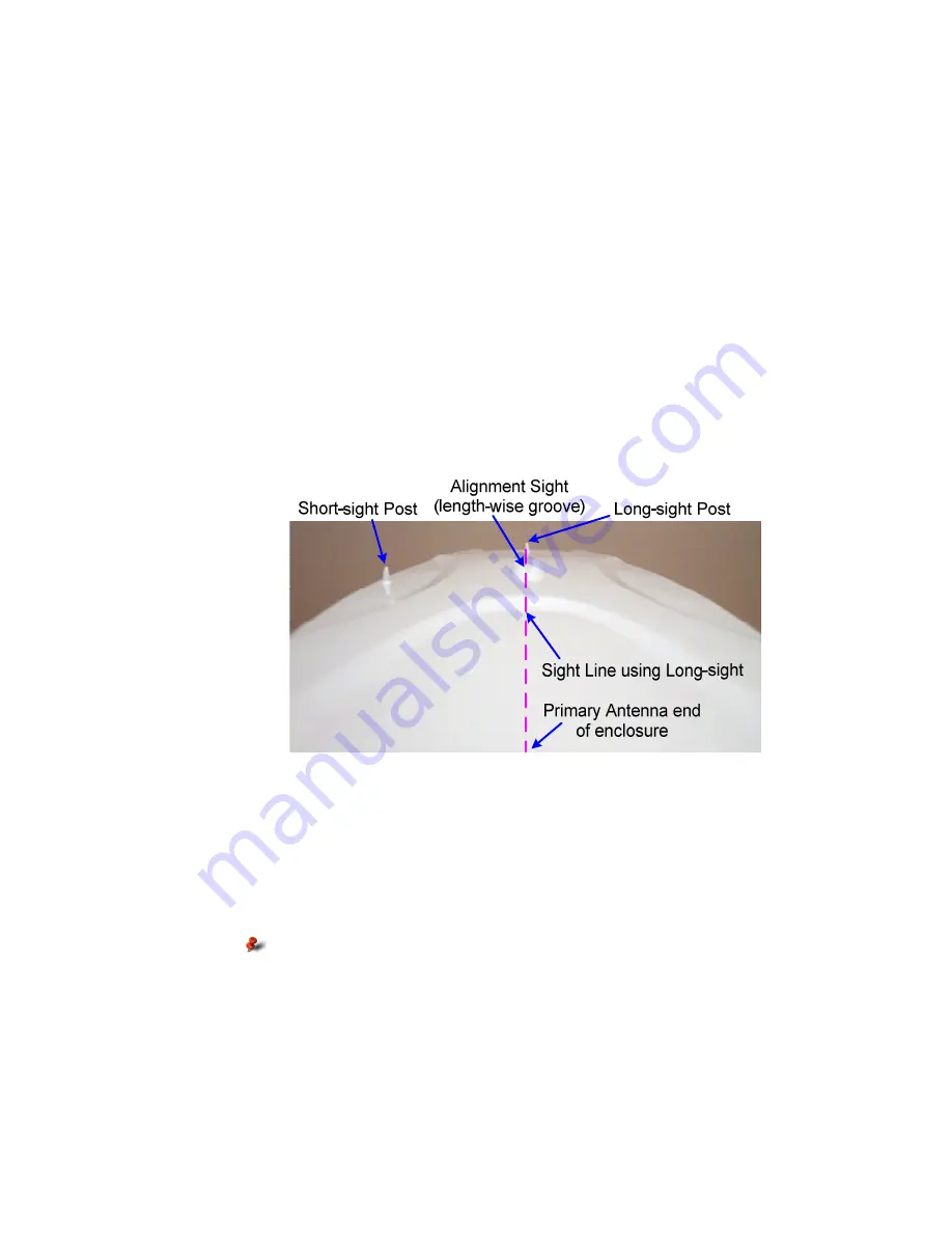
The top of the G2’s enclosure incorporates two small positioning posts and an alignment
sight, to assist in aligning the unit’s orientation. Perform the following steps to align the
unit:
•
look along the top of the unit’s top cover & across the sight:
– from the end without a post:
centre the other end’s post (the Long-sight shown in Figure 8, Figure 7
and Figure 13) in the length-wise groove in the Alignment sight
– from the middle of the long side without a post:
centre the other edge’s post (the Short-sight, shown in the same figures)
in the width-wise groove in the Alignment sight
•
The sight-line you see is the centreline of the unit.
•
adjust the direction of the unit’s sight-line to be parallel to the vessel’s centreline:
– either the fore-aft or athwart ships line, whichever you have chosen to use
– or perpendicular to one of those centrelines
•
alignment accuracy when using the Long-sight method is approximately ± 1°
•
using the Short-sight method, alignment is accurate to approximately ± 2.5°
Figure 13 – Long-sight Alignment
If another accurate source of heading data is available on your vessel, you may record
and correct any bias in the G2’s alignment difference between the G2’s initial reported
heading and that of the other accurate heading device. To do so, enter the difference
value in the G2’s heading bias parameter. A bias value can also be obtained by doing a
traditional “box the compass” run
.
Alternatively, you may wish to physically adjust the direction of the G2’s enclosure, by
that other heading device bias value, so that the G2 does not have any bias in its
alignment.
Using the G2’s heading bias parameter is usually the easier to
achieve
Wiring for NMEA 0183 system
A single 18 pin cable allows power and NMEA data & control signals from & to the unit.
The terminated connector side of the cable is an environmentally sealed, mechanically-
keyed/locking connector; the other end is un-terminated, and requires field stripping and
tinning for connection to a distribution box.
The cable can be wired to other equipment using NMEA 0183 input as navigation data.
Summary of Contents for Vector G2
Page 2: ......
Page 6: ...ComNav G2 G2B Installation Operation Document PN 29010093 V1 5 4 16 December 2016...
Page 12: ...ComNav G2 G2B Installation Operation Document PN 29010093 V1 5 10 16 December 2016...
Page 14: ...ComNav G2 G2B Installation Operation Document PN 29010093 V1 5 12 16 December 2016...
Page 19: ...ComNav G2 G2B Installation Operation Document PN 29010093 V1 5 17 16 December 2016...
Page 43: ...ComNav G2 G2B Installation Operation Document PN 29010093 V1 5 41 16 December 2016 Operation...
Page 44: ...ComNav G2 G2B Installation Operation Document PN 29010093 V1 5 42 16 December 2016...
Page 59: ...ComNav G2 G2B Installation Operation Document PN 29010093 V1 5 57 16 December 2016...
Page 83: ...ComNav G3 G3B Installation Operation Document PN 29010093 V1 5 81 16 December 2016...
Page 84: ...ComNav G3 G3B Installation Operation Document PN 29010093 V1 5 82 16 December 2016 Index...
Page 85: ...ComNav G3 G3B Installation Operation Document PN 29010093 V1 5 83 16 December 2016...
Page 87: ...ComNav G2 G2B Installation Operation Document PN 29010093 V1 5 85 16 December 2016...
Page 88: ...ComNav G2 G2B Installation Operation Document PN 29010093 V1 5 86 16 December 2016 User Notes...
Page 89: ...ComNav G2 G2B Installation Operation Document PN 29010093 V1 5 87 16 December 2016...


