background image

INS_CLFE(X)EO(C,U)_REV–   10/27/11   PAGE 8

INSTALLATION AND OPERATION MANUAL 

CLFE(X)EO(C,U) SERIES

TECH SUPPORT: 1.888.678.9427

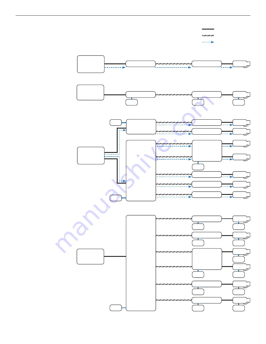
APPLICATION DIAGRAMS

Note: Coaxial applications use CLFE(X)EO

C

 modules; UTP applications use CLFE(X)EO

U

 modules.

PoE Pass-Through Mode

Non-PoE Mode

Multichannel Non-PoE Application

Multichannel PoE Application

IMPORTANT NOTE. PLEASE READ.

 The applications are 

shown as general representations only and are not intended 

to show detailed network topologies. Your actual network 

will differ, requiring changes or perhaps additional network 

equipment to accommodate the systems as illustrated. 

Please contact ComNet’s Design Center to discuss your 

specific requirements.

PoE  

Ethernet Switch 

or Midspan

Local

Remote

CLFE1EO(C,U)

CLFE1EO(C,U)

PoE Camera

Ethernet  

Switch

Local

Remote

Power

Power

Power

CLFE1EO(C,U)

CLFE1EO(C,U)

IP Camera

Ethernet  

Switch

Local

Remote

CLFE4EO(C,U)

CLFE16EO(C,U)

CLFE1EO(C,U)

CLFE1EO(C,U)

CLFE1EO(C,U)

CLFE1EO(C,U)

Power

IP Camera

Power

Power

IP Camera

Power

Power

IP Camera

Power

Power

IP Camera

Power

Power

IP Camera

Power

Power

IP Camera

Power

PoE Camera

PoE Camera

PoE Camera

PoE Camera

PoE Camera

PoE Camera

PoE Camera

Local

Remote

Power

CLFE8EO(C,U)

CLFE4EO(C,U)

CLFE4EO(C,U)

CLFE1EO(C,U)

CLFE1EO(C,U)

CLFE1EO(C,U)

CLFE1EO(C,U)

CLFE1EO(C,U)

Power

Power

PoE  

Ethernet Switch 

or Midspan

Ethernet Connection

PoE Power

Extended Connection

Summary of Contents for Copper Line CLFE16EOC

Page 1: ...witches are provided for user selection of local or remote 10 or 100Mbps and 1 pair or 4 pair UTP settings Bi color Red Green LED indicators are provided for rapidly ascertaining equipment operating status Table 2 on Page 9 describes the LED indicators for each light on the unit The CLFE8EO C U and CLFE16EO C U are 1RU rack mountable units The CLFE4EO C U units are interchangeable between stand al...

Page 2: ...VDC OR 24 VAC Power Consumption 1 5 W Power Operates on PoE power OR 9 to 36 VDC OR 24 VAC Power Consumption 1 5 W Black w White Stripe AC or DC Black AC or DC Black w White Stripe AC or DC Black AC or DC Local Remote push button See Installation Instructions Step 3 Local Remote DIP switch See Installation Instructions Step 3 10 100 data rate DIP switch See Installation Instructions Step 1 Wire pa...

Page 3: ...RFACE OR RACK MOUNT COAX UNIT CH1 EXT DISTANCE CH1 ETHERNET CH2 EXT DISTANCE CH2 ETHERNET CH3 EXT DISTANCE CH3 ETHERNET CH4 EXT DISTANCE CH4 ETHERNET Operating Power 9 to 15 VDC Power Consumption 5W Black w White Stripe DC Black DC Local Remote push button See Installation Instructions Step 3 10 100 data rate DIP switch See Installation Instructions Step 1 Local Remote DIP switch See Installation ...

Page 4: ...NEL SURFACE OR RACK MOUNT UTP UNITS CH1 EXT DISTANCE CH1 ETHERNET CH2 EXT DISTANCE CH2 ETHERNET CH3 EXT DISTANCE CH3 ETHERNET CH4 EXT DISTANCE CH4 ETHERNET Operating Power 9 to 15 VDC Power Consumption 5W Black w White Stripe DC Black DC Local Remote DIP switch See Installation Instructions Step 3 Wire pair DIP switch See Installation Instructions Step 2 Data rate DIP switch See Installation Instr...

Page 5: ...IP switch See Installation Instructions Step 1 Data rate DIP switch See Installation Instructions Step 1 CH4 EXT DISTANCE CH5 ETHERNET CH8 EXT DISTANCE CH1 ETHERNET CH3 EXT DISTANCE CH6 ETHERNET CH7 EXT DISTANCE CH2 ETHERNET CH2 EXT DISTANCE CH7 ETHERNET CH6 EXT DISTANCE CH3 ETHERNET CH1 EXT DISTANCE CH8 ETHERNET CH5 EXT DISTANCE CH4 ETHERNET Operating Power 9 to 15 VDC Power Consumption 10W Black...

Page 6: ...10 EXT DISTANCE CH7 ETHERNET CH15 ETHERNET CH6 EXT DISTANCE CH14 EXT DISTANCE CH3 ETHERNET CH11 ETHERNET CH1 EXT DISTANCE CH9 EXT DISTANCE CH8 ETHERNET CH16 ETHERNET CH5 EXT DISTANCE CH13 EXT DISTANCE CH4 ETHERNET CH12 ETHERNET FIGURE 9 CLFE16EOC MULTICHANNEL RACK COAX UNITS Data rate DIP switch See Installation Instructions Step 1 Data rate DIP switch See Installation Instructions Step 1 Data rat...

Page 7: ...TANCE CH9 EXT DISTANCE CH8 ETHERNET CH16 ETHERNET CH5 EXT DISTANCE CH13 EXT DISTANCE CH4 ETHERNET CH12 ETHERNET FIGURE 10 CLFE16EOU MULTICHANNEL RACK UTP UNITS Data rate DIP switch See Installation Instructions Step 1 Data rate DIP switch See Installation Instructions Step 1 Data rate DIP switch See Installation Instructions Step 1 Data rate DIP switch See Installation Instructions Step 1 Wire pai...

Page 8: ...he systems as illustrated Please contact ComNet s Design Center to discuss your specific requirements PoE Ethernet Switch or Midspan Local Remote CLFE1EO C U CLFE1EO C U PoE Camera Ethernet Switch Local Remote Power Power Power CLFE1EO C U CLFE1EO C U IP Camera Ethernet Switch Local Remote CLFE4EO C U CLFE16EO C U CLFE1EO C U CLFE1EO C U CLFE1EO C U CLFE1EO C U Power IP Camera Power Power IP Camer...

Page 9: ...e the Local Remote push button switch coax units only and set to the same setting as the dip switch The factory setting for these switches is RM The CLFE8EO C U and CLFE16EO C U units are preconfigured as Local devices 4 CONNECT EXTENDED WIRING Connect Extended Distance Port to field wiring 5 CONNECT NETWORK WIRING Using CAT5 5e connect Local unit to network and Remote unit to camera 6 CONNECT POW...

Page 10: ...se testing mirroring installations Factors such as coaxial copper cable quality the number of connectors splices in the cable run the use of PoE and environmental conditions encountered within the installation may affect the actual transmission distance and should be taken into consideration Due to advanced negotiation signaling required in IEEE 802 3at applications Pass through applications are l...

Page 11: ...1 65in 0 8cm 0 31in 0 4cm 0 16in 0 62cm 0 24in 6 37cm 2 50in 13 2cm 5 2in 11 9cm 4 7in 15cm 5 9in 7 5cm 2 9in 0 63cm 0 25in 2 75cm 1 1in 44 45cm 17 50in 48 26cm 19 0in 15 44cm 6 08in 1 9cm 0 75in 4 37cm 1 72in 1 9cm 0 75in PRODUCT DIMENSIONS The CLFE1EO C U is supplied as a standalone surface mount small size module The CLFE4EO C U is supplied as a standalone surface rack ComFit module The CLFE8EO...

Page 12: ...bient Therefore consideration should be given to installing the equipment in an environment compatible with the maximum ambient temperature Tma specified by the manufacturer B Reduced Air Flow Installation of the equipment in a rack should be such that the amount of air flow required for safe operation of the equipment is not compromised 2014CommunicationNetworks AllRightsReserved ComNet the ComNe...

Reviews: