6-7-06 - Fifth Proof
3-18
Pre-Start Inspection and Operation
Removal of Attachment
1. Lower the attachment onto a firm, level surface.
2. Shut off the machine engine.
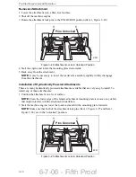
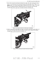
3. Rotate the attachment lock pins to the UNLOCKED position (Item 1, Figure 3–24).
Figure 3–24 Attachment Locks in Unlocked Position
4. Start the engine and rotate the mounting plate downwards.
5. Back away from the attachment.
NOTE:
It may be necessary to lower the loader arm assembly slightly to fully disengage
from the attachment.
Installation of Hydraulically Powered Attachments
There are many hydraulically powered attachments available that are very easy to install. To
install any of these attachments:
1. Position the attachment on a level surface.
NOTE:
Clean the lower edge of the female attachment mounting plate to remove any debris
that might interfere with the attachment installation.
2. Start the machine engine, lower the loader arm and tilt the mounting plate forwards.
NOTE:
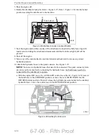
Make sure that both of the attachment lock pins (Item 1, Figure 3–25 and Item 3,
Figure 3–26) are in the “unlocked” position.
Figure 3–25 Attachment Locks in Unlocked Position
1
1
Pi
n
s U
n
l
o
ck
ed
2021
1
1
Pi
n
s U
n
l
o
ck
ed
2021
Summary of Contents for BOXER 427 Operators
Page 2: ...6 7 06 Fifth Proof...
Page 6: ...6 7 06 Fifth Proof iv Mertz Manufacturing LLC P O Box 150 Ponca City OK 74602 Affix Stamp Here...
Page 8: ...6 7 06 Fifth Proof vi...
Page 18: ...6 7 06 Fifth Proof 1 8 Safety Precautions...
Page 31: ...6 7 06 Fifth Proof 3 5 Pre Start Inspection and Operation Figure 3 4 Lubrication Points 2128...
Page 52: ...6 7 06 Fifth Proof 3 26 Pre Start Inspection and Operation...
Page 74: ...6 7 06 Fifth Proof 4 22 Routine Service and Maintenance...
Page 85: ...6 7 06 Fifth Proof...


