CompAir UK Ltd
PUBLICATION 98407/1050
Page 33
10
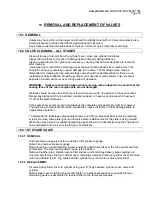
REMOVAL AND REPLACEMENT OF VALVES
10.1 GENERAL
Valves may have a thin carbon layer and should be slightly moist with oil. Valve maintenance is a
simple procedure provided the following guidelines are observed.
Keep a spare oiled and maintained set of valves in store for quick compressor servicing.
10.2 VALVE CLEANING – ALL STAGES
Clean all traces of old joint from the cylinder cover, valve and cylinder joint faces.
Inspect all joint faces for cracks or damage liable to impair sealing efficiency.
Clean or decarbonize the cylinder as necessary, ensuring that all loose deposits are removed
after cleaning.
Valve cleaning is restricted to cleaning any excessive carbon deposits from valve ports. This
should be done very carefully to avoid damage to the valve. The first stage valve may be
dismantled for cleaning but the second stage valve should not be dismantled as there are no
replacement parts available. Providing synthetic oil is used as recommended, only very small
deposits of carbon will occur over a long period of operation.
WARNING:- Great care should be taken when removing carbon deposits to ensure that the
seating faces of the valve components are not damaged.
All faces should be clean and bright over their whole area, with no evidence of uneven contact.
Renew any plates which are indented, cracked, warped, or have wear grooves which exceed
1/10th of the plate thickness.
If the seats show severe wear or indentations the complete valve assembly must be renewed.
The remaining components should be checked for cracks, distortion or other damage liable to
impair valve operation.
To dismantle the first stage valve separate valve guard from valve seat after removing retaining
screws. Remove valve plate. Ensure that valve plate is
not
reversed if the plate is being reused.
Wash the valve parts in a suitable degreasing agent. Blow dry, reassemble using the original or a
new valve plate and re-oil prior to placing in compressor.
10.3 1ST STAGE VALVE
10.3.1 REMOVAL
Undo pressure gauge pipe at the coupling on the pressure gauge.
Detach and remove pressure gauge.
Remove main fan guard retaining screws and slide guard forwards over the fan and remove from
compressor. The inner mesh guard may be left in position.
Remove breather pipe. Detach suction filter silencer and first stage delivery pipe coupling nut.
Unscrew and remove the four cylinder cover retaining screws and remove cylinder cover. Remove
valve and discard the 'O' ring seals between cylinder cover and valve, valve and cylinder.
10.3.2 REPLACEMENT
Fit valve and cylinder cover to cylinder using new 'O' rings between cylinder cover, valve and
cylinder.
Refit cylinder cover retaining screws and tighten in a diagonal sequence to specified torque.
Remaining parts are assembled in reverse order to the removal procedure.
Summary of Contents for 5211.2.IA
Page 2: ......
Page 14: ...CompAir UK Ltd PUBLICATION 98407 1050 Page 12...
Page 16: ...CompAir UK Ltd PUBLICATION 98407 1050 Page 14 REMARKS DATE REMARKS DATE...
Page 22: ...CompAir UK Ltd PUBLICATION 98407 1050 Page 20...
Page 32: ...CompAir UK Ltd PUBLICATION 98407 1050 Page 30...
Page 38: ...CompAir UK Ltd PUBLICATION 98407 1050 Page 36...
Page 61: ......


