CompAir UK Ltd.
APP167 SAFETY VALVE I&O INSTRUCTIONS
Page 1
APP167 .DOC
Installation and Operating Instructions
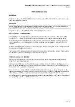
SAFETY VALVES
INTRODUCTION
Due consideration should be taken of climatic. Process or other conditions which might adversely affect
the performance of the safety valve. Installation must be undertaken by qualified technicians and to good
engineering practice. In addition, user's attention is drawn to our joint responsibility to ensure that the
Health and Safety at Work Act is not contravened by incorrect installation. Commissioning or servicing. It
is important that the valve to be installed is correct in every aspect, i.e. set pressure, size, material and
type etc. for the application.
STORAGE OF VALVE BEFORE INSTALLATION
Valves should be stored preferably between-5°C and +25°C and a relative humidity of less that 75%. Very
moist or dry conditions should be avoided. If a safety valve is installed after six months, or more, of
storage, it must be subjected to functional test before commissioning. Thread protectors should not be
removed until immediately, prior to testing or installation, as they also prevent the ingress of foreign
matter, which could
harm the valve.
INSTALLATION
VALVE INLET
: Under no circumstances should it be possible to isolate the safety valve from the protected
system. Safety valves should be mounted as close as possible to the protected system. The connecting
pipe should be straight and as short as possible. The inlet line to the safety valve should have an effective
area of flow, at least equal to that
of the safety valve inlet. CompAir Limited should be consulted if the
safety valve is to be mounted in any position other than vertically. The maximum pressure drop through
the inlet line to the safety valve should not exceed 3% of the set pressure when the valve is discharging at
its rated capacity.
VALVE OUTLET
:
No isolating devices shall be fitted to the outlet pipe. Discharge pipes should be as short
as possible and of such a size that the pressure developed therein not reduce the relieving capacity.
Ensure arrows indicating the direction of the flow are pointing in the correct direction. The cross-sectional
area of the discharge pipe should not be less than the area of the safety valve outlet. Where safety valves
are discharged into a manifold, the manifold must be capable of accommodating simultaneous discharge
of all valves connected to the manifold. Atmospheric discharge or discharge pipes should terminate at a
location which will not cause a hazard to personnel, particular attention being given to hazardous fluids or
particles.
GENERAL
:
Inlet and outlet piping should be capable of supporting the safety, valve so that no
unacceptable mechanical load or vibration is transmitted to the valve, and be sufficiently strong to
withstand 'the effects of the reaction forces when the valve is discharging. All pipework or pressure
vessels to which the safety valve is connected should be thoroughly cleaned before fitting the safety valve,
to ensure that foreign matter does not pass through the valve.
Particular care should be taken with the
use of scaling compounds and P.T.F.E. tape to ensure that they do not enter the valve.
Atmospheric discharge valves should not be painted or coated with any substance, which could possibly
obstruct or restrict free and full discharge through the valve. Suitable protection should be provided to
prevent environmental build up or ingress of foreign matter. Any condition that could lead to blockage of
discharge piping or discharge ports on safety valves must be avoided. Where appropriate, discharge pipes
should be provided to a non-hazardous location. Where there is a possibility of a liquid head forming in a
discharge pipe, a drain should be provided which leads to a safe discharge location. To prevent
unnecessary lifting of the safety valve it is recommended that there is a margin of at least 10% between
the maximum operating pressure and the set pressure of the safety valve.
FUNCTIONAL TESTING
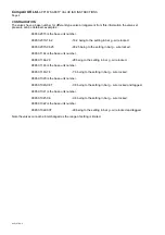
Once installed in service. Valves should be tested at least once every six months to ensure free
movement of parts. This should be carried out by operating the easing gear when the valve is under a
pressure of not less than 75'% of the set pressure. Where valves are supplied without easing gear, the
test should be in accordance with the full functional test described overleaf. Due regard must be paid to
the safety personnel. Testing should not create a hazard, particular attention being given to foreign matter
located in discharge outlets.
Summary of Contents for 5280D.1.IAC
Page 3: ...DATE REMARKS DATE REMARKS logsheet5280 d...
Page 9: ...CompAir UK Ltd 5280D Compressor Publication 98407 1440 Page 6 1440 doc...
Page 29: ...CompAir UK Ltd 5280D Compressor Publication 98407 1440 Page 26 1440 doc...
Page 33: ...CompAir UK Ltd 5280D Compressor Publication 98407 1440 Page 30 1440 doc...
Page 39: ......
Page 40: ......
Page 41: ......
Page 42: ...CompAir UK Ltd 5280D Compressor Publication 98407 1440 Page 36 1440 doc...
Page 44: ...CompAir UK Ltd 5280D Compressor Publication 98407 1440 Page 38 1440 doc CRANKCASE 1...
Page 46: ...CompAir UK Ltd 5280D Compressor Publication 98407 1440 Page 40 1440 doc CRANKCASE 2...
Page 48: ...CompAir UK Ltd 5280D Compressor Publication 98407 1440 Page 42 1440 doc CRANKCASE 3...
Page 50: ...CompAir UK Ltd 5280D Compressor Publication 98407 1440 Page 44 1440 doc CYLINDER 1st STAGE...
Page 52: ...CompAir UK Ltd 5280D Compressor Publication 98407 1440 Page 46 1440 doc SUCTION VALVE COVER...
Page 60: ...CompAir UK Ltd 5280D Compressor Publication 98407 1440 Page 54 1440 doc CROSSHEAD 1st STAGE...
Page 62: ...CompAir UK Ltd 5280D Compressor Publication 98407 1440 Page 56 1440 doc PISTON 1st STAGE...
Page 64: ...CompAir UK Ltd 5280D Compressor Publication 98407 1440 Page 58 1440 doc GLAND 1st STAGE...
Page 66: ...CompAir UK Ltd 5280D Compressor Publication 98407 1440 Page 60 1440 doc OIL PUMP...
Page 68: ...CompAir UK Ltd 5280D Compressor Publication 98407 1440 Page 62 1440 doc OIL PUMP FILTER...
Page 70: ...CompAir UK Ltd 5280D Compressor Publication 98407 1440 Page 64 1440 doc INTERCOOLER...
Page 72: ...CompAir UK Ltd 5280D Compressor Publication 98407 1440 Page 66 1440 doc 1st STAGE PIPE WORK...
Page 74: ...CompAir UK Ltd 5280D Compressor Publication 98407 1440 Page 68 1440 doc...
Page 76: ......
Page 77: ......
Page 78: ......
Page 79: ......
Page 80: ......
Page 81: ......
Page 82: ......
Page 83: ......
Page 84: ......
Page 85: ......
Page 86: ...CompAir UK Ltd 5280D Compressor Publication 98407 1440 Page 70 1440 doc...
Page 94: ...CompAir UK Ltd 5280D Compressor Publication 98407 1440 Page 72 1440 doc...
Page 98: ...App 408 Customer PET controller installation guide user s manual Page 2 App 408C 98155 1015...
Page 120: ...CompAir UK Ltd APP 004 ANTI VIBRATION MOUNTS Page 2 app004 doc...
Page 122: ...CompAir UK Ltd PUBLICATION APP070 PRESSURE GAUGES GENERAL Page 2 app070 doc...
Page 128: ...CompAir UK Ltd PUBLICATION APP 138 3 WAY SOLENOID VALVES PS2197 Page 2 app138 doc...
Page 130: ...CompAir UK PUBLICATION APP034 ELECTRIC MOTOR MAINTENANCE GENERAL Page 2 APP034 doc...
Page 133: ...CompAir UK Ltd 5280D Compressor Publication 98407 1440 Page 74 1440 doc...


