CompAir UK Ltd
5280D Compressor Publication 98407.1440
Page 18
1440.doc
7.3
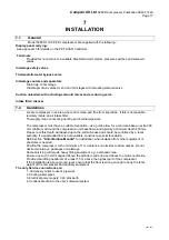
Cooling Water System
Install a flow indicator and an isolating valve (for maintenance purposes) in the cooling water supply line.
If the quality of cooling water is poor, treat it to prevent corrosion and scale formation. Protect re-
circulating cooling systems against freezing by using proprietary anti-freeze with inhibitors.
The cooling water should be clean and silt free. Arrange the water supply so that there is a minimum
head of 6 m.
It is recommended that a water pump is fitted, in which case it must be inter-locked with the main starter.
If the cooling water is drawn from the site cooling water service, install a solenoid operated stop valve
(again inter-locked with main starter), or pneumatic operated stop valve in the supply line to the
compressor. Never allow cooling water to circulate when the compressor has stopped; this can cause
moisture in the compressed air to condense and seriously affect lubrication.
The quantity of cooling water required depends upon the compressor input power needed. A
temperature rise of approximately 10 ~ 12 °C is suggested for adequate cooling and prevent initial
condensation. To achieve this rise the water flowrate needed is 75 litre/hour per kW input power.
Always check the hardness and quality of the water used.
If a cooling tower is used, seek advice from local specialist organisations for precautions necessary to
prevent a health risk from bacterial growth.
7.4 Vibration
If complete isolation from the building or other equipment is required, mount the compressor and drive
motor, etc. on a common baseframe carried on anti-vibration mounts. Include a pipework vibration
eliminator in the air delivery pipework and a flexible section in the cooling water service piping
immediately before the connection to the compressor.
5.4.1 Vibration eliminators
typically consist of a length of flexible thin walled bellows section pipe
carried between two rigid flanged connecting pieces. The flexible section is braided for protection.
Regularly inspect eliminators for damage or abrasion. Provide adequate support immediately
downstream of the vibration eliminator, independent of the compressor unit to isolate it from induced
vibration.
7.5 Air
Receiver
It is normal practice to install a receiver of appropriate capacity between this type of compressor and the
user's pipework. As well as providing pulse free pressure for the air system it allows simple collection of
any remaining moisture.
A receiver is essential if air usage is intermittent or fluctuates rapidly such that instantaneous demand
exceeds compressor output.
As a guide select a receiver size sufficient to store air for between one and one and a half minutes
usage. The receiver size can then be calculated from the volume of air delivered by the compressor in
one minute.
For intermittently high air consumption use the same calculation and multiply by a factor of 3.
7.6 Corrosion
Protection
Before despatch all compressors are protected against the effects of moisture.
If all blanking covers and protective tapes remain secure and undamaged the effective life of these
processes is 12 months from the despatch date.
Summary of Contents for 5280D.1.IAC
Page 3: ...DATE REMARKS DATE REMARKS logsheet5280 d...
Page 9: ...CompAir UK Ltd 5280D Compressor Publication 98407 1440 Page 6 1440 doc...
Page 29: ...CompAir UK Ltd 5280D Compressor Publication 98407 1440 Page 26 1440 doc...
Page 33: ...CompAir UK Ltd 5280D Compressor Publication 98407 1440 Page 30 1440 doc...
Page 39: ......
Page 40: ......
Page 41: ......
Page 42: ...CompAir UK Ltd 5280D Compressor Publication 98407 1440 Page 36 1440 doc...
Page 44: ...CompAir UK Ltd 5280D Compressor Publication 98407 1440 Page 38 1440 doc CRANKCASE 1...
Page 46: ...CompAir UK Ltd 5280D Compressor Publication 98407 1440 Page 40 1440 doc CRANKCASE 2...
Page 48: ...CompAir UK Ltd 5280D Compressor Publication 98407 1440 Page 42 1440 doc CRANKCASE 3...
Page 50: ...CompAir UK Ltd 5280D Compressor Publication 98407 1440 Page 44 1440 doc CYLINDER 1st STAGE...
Page 52: ...CompAir UK Ltd 5280D Compressor Publication 98407 1440 Page 46 1440 doc SUCTION VALVE COVER...
Page 60: ...CompAir UK Ltd 5280D Compressor Publication 98407 1440 Page 54 1440 doc CROSSHEAD 1st STAGE...
Page 62: ...CompAir UK Ltd 5280D Compressor Publication 98407 1440 Page 56 1440 doc PISTON 1st STAGE...
Page 64: ...CompAir UK Ltd 5280D Compressor Publication 98407 1440 Page 58 1440 doc GLAND 1st STAGE...
Page 66: ...CompAir UK Ltd 5280D Compressor Publication 98407 1440 Page 60 1440 doc OIL PUMP...
Page 68: ...CompAir UK Ltd 5280D Compressor Publication 98407 1440 Page 62 1440 doc OIL PUMP FILTER...
Page 70: ...CompAir UK Ltd 5280D Compressor Publication 98407 1440 Page 64 1440 doc INTERCOOLER...
Page 72: ...CompAir UK Ltd 5280D Compressor Publication 98407 1440 Page 66 1440 doc 1st STAGE PIPE WORK...
Page 74: ...CompAir UK Ltd 5280D Compressor Publication 98407 1440 Page 68 1440 doc...
Page 76: ......
Page 77: ......
Page 78: ......
Page 79: ......
Page 80: ......
Page 81: ......
Page 82: ......
Page 83: ......
Page 84: ......
Page 85: ......
Page 86: ...CompAir UK Ltd 5280D Compressor Publication 98407 1440 Page 70 1440 doc...
Page 94: ...CompAir UK Ltd 5280D Compressor Publication 98407 1440 Page 72 1440 doc...
Page 98: ...App 408 Customer PET controller installation guide user s manual Page 2 App 408C 98155 1015...
Page 120: ...CompAir UK Ltd APP 004 ANTI VIBRATION MOUNTS Page 2 app004 doc...
Page 122: ...CompAir UK Ltd PUBLICATION APP070 PRESSURE GAUGES GENERAL Page 2 app070 doc...
Page 128: ...CompAir UK Ltd PUBLICATION APP 138 3 WAY SOLENOID VALVES PS2197 Page 2 app138 doc...
Page 130: ...CompAir UK PUBLICATION APP034 ELECTRIC MOTOR MAINTENANCE GENERAL Page 2 APP034 doc...
Page 133: ...CompAir UK Ltd 5280D Compressor Publication 98407 1440 Page 74 1440 doc...

