26
6.4
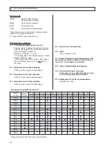
Electrical connection
Installed
Nominal
Fuse protection
Wire
380 V/50 Hz
nominal
motor power
(slow-blow
cross-section
motor power
ventilator A (W)
fuse)
at 30 °C
[kW]
[kW]
[A]
[mm
2]
A
W
A
W
L37S
37
1,1 (0,37)
100
80
3 x 35 /PE 16
3 x 25 /PE 16
L45
45
1,1 (0,37)
125
100
3 x 50 /PE 25
3 x 35 /PE 16
L55
55
2,2 (0,37)
125
125
3 x 50 /PE 25
3 x 50 /PE 25
L75
75
2,2 (0,37)
160
160
3 x 70 /PE 35
3 x 70 /PE 35
Installed
Nominal
Fuse protection
Wire
400/415 V/50 Hz
nominal
motor power
(slow-blow
cross-section
motor power
ventilator A (W)
fuse)
at 30 °C
[kW]
[kW]
[A]
[mm
2]
A
W
A
W
L37S
37
1,1 (0,37)
80
80
3 x 25 /PE 16
3 x 25 /PE 16
L45
45
1,1 (0,37)
100
100
3 x 35 /PE 16
3 x 35 /PE 16
L55
55
2,2 (0,37)
125
125
3 x 50 /PE 25
3 x 50 /PE 25
L75
75
2,2 (0,37)
160
160
3 x 70 /PE 35
3 x 70 /PE 35
Recommended supply line cross-sections and fuses
6. Preparations for commissioning
Notes on the table:
We do not know the cable type used by you, its
length and the installation conditions (temperatures,
grouping). The table above can therefore only be re-
garded as a guideline.
The supply line cross-sections given in the table cor-
respond to VDE 0100, part 523 - group 2 (multi-wire
cables or grouped, individual wires at 30 °C and a
max. line length of 50 m). In the case of differing con-
ditions (cable length, temperature and grouping), the
cable cross-sections have to be selected in line with
DIN VDE 0298, part 4, which also refers to the cable
type.
The setting value of the motor protective switch for the
fan drive depends on the individual ambient and instal-
lation conditions on site. For safety reasons, the exact
setting values should be obtained from the manufactur-
er.
I
setting
= I
nom
x 1.15 x voltage correction, if required
I
nom
see nameplate
Compressed air stations are finished in the factory ac-
cording to standard EN60204 (industrial machinery).
Please observe the following notes:
Danger
.
The customer has to connect a main switch in the
incoming line of the screw compressor unit (unless
factory-mounted as special accessories) (DIN EN
1012 - 1). If this switch does not assume short-circuit
and overload protection functions for the system,
suitable back-up fuses must be installed (see table)
The main switch must meet the requirements of
safety standard EN 60 204-1/Art. 5.3 (electrical
equipment of machinery).
The electrical connections and the protective meas-
ures have to be carried out in line with VDE regula-
tions or the national stipulations in your country.
Generally, additional rules of the respective electri-
cal power supplier have to be observed.
If the erection conditions of the system deviate
from the conditions described in EN60204, please
contact your technical consultant.
The connections must be made by an authorized
specialist.
Attention: Interference voltage! If external electric
circuits, which cannot be cut out via the main switch,
are connected to the control, these have to be identi-
fied according to EN60204. Warning signs have to be
fixed near the main switch and near these electric
circuits. In addition, these conductors have to be laid
separately and/or identified by colours.
Work on control cabinets may only be carried out
by electrotechnical specialists.


