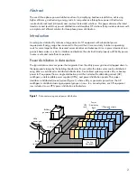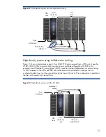
Figure 8
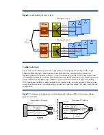
. Load balancing at the row level
PDR
UPS Rack
DPs
60+ kVA
15 kVA
15 kVA
15 kVA
15 kVA
AC
Mains
UPSs
ITE
Rack
ITE
Rack
ITE
Rack
ITE
Rack
PDR
UPS Rack
DPs
60+ kVA
20 kVA
20 kVA
20 kVA
ITE
Rack
ITE
Rack
ITE
Rack
UPSs
Equipment row 2
Equipment row 1
Cable reduction
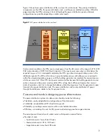
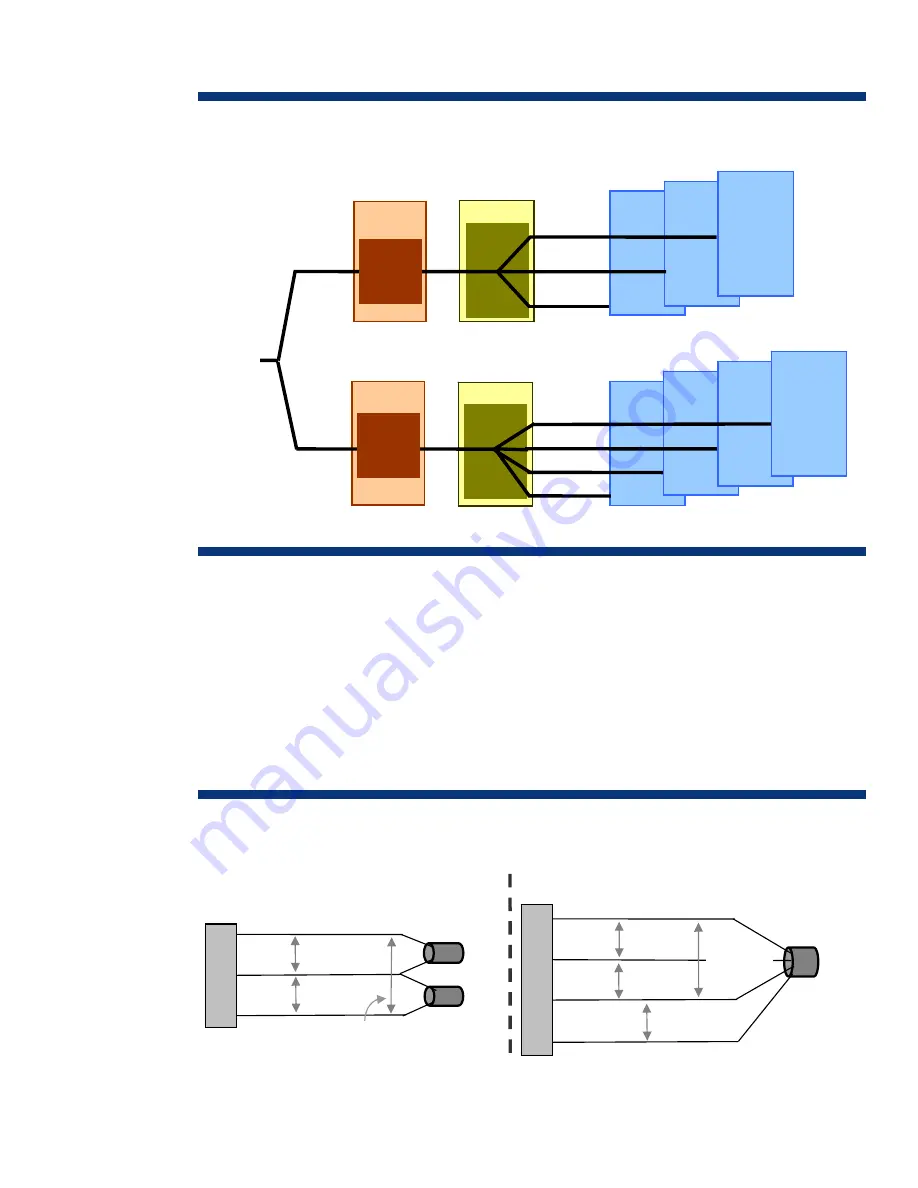
Figure 9 shows the differences between single-phase and three-phase AC cabling. With a single-
phase distribution system, cables from each side (branch) of the neutral point are routed from
distribution panels to equipment groups or racks. Load balancing is more difficult, requiring at least
two distribution cables per rack and more careful planning. Racks receiving two AC buses will require
power distribution units (PDUs) to be installed in pairs to achieve a balance of equipment loading.
With three-phase distribution, each equipment rack requires only one cable providing three hot wires
and one neutral conductor. Load balancing is possible with one three-phase PDU, which simplifies the
configuration.
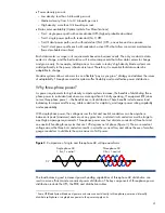
Figure 9
. Comparison of single-phase and three-phase AC cabling with North American voltages
(ground not shown)
Single-phase AC cabling
Three-phase AC cabling
Neutral
110 VAC
(hot)
Single-phase
110 VAC
110 VAC
(hot)
110 VAC
(hot)
110 VAC
(hot)
Split-phase
208 VAC
Split-phase
208 VAC
Distribution Pan
el
Single-phase
110 VAC
Neutral
Split-phase
208 VAC
Bus A
Bus B
Split-phase
208 VAC
Single-phase
110 VAC
Distribution Pan
el
110 VAC
(hot)
To
PDUs
To
PDUs
9


