background image

2-24

Hardware Upgrades

Compaq Confidential - Need to Know Required

Writer: Kristen Cover Part Number: 178147-002 File Name: e-UpgradesCMT.doc

Last Saved On: 08/21/00 8:40 AM Last Saved By: Martha Rockecharlie

8.

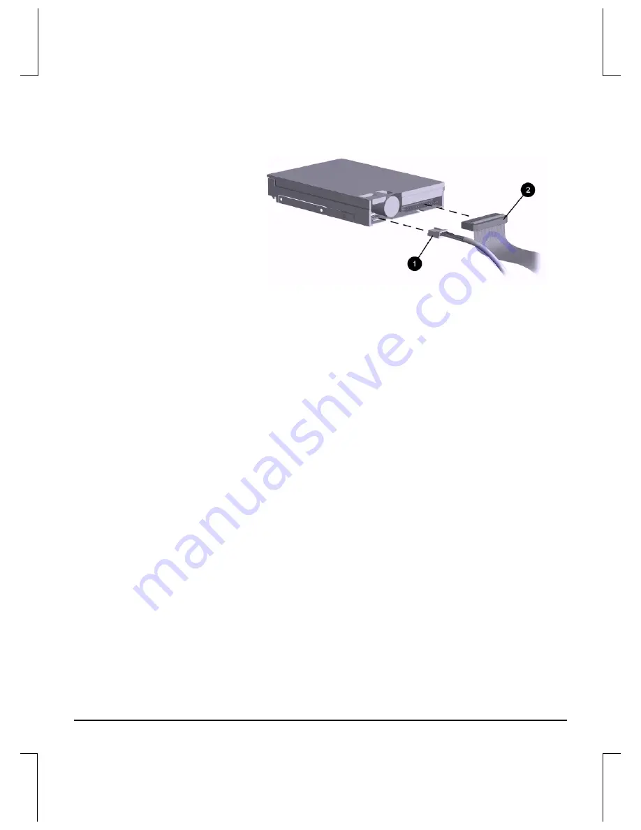
Connect the drive power

1

and signal

2

cables.

Connecting the Drive Cables

9.

Remove the appropriate bezel blank from the subpanel inside the
front bezel. (Refer to the section “Removing Bezel Blanks.”)

10. Replace the computer access panel.

11. Reconfigure the computer, if necessary. Refer to Chapter 1,

“Installation Guidelines,” for more information.

Installing a Hard Drive into a 3.5-inch Drive Bay

Compaq does not support mixing IDE and SCSI hard drives
in the same system. If you are replacing a hard drive in bay 4
or bay 5, it should be of the same type.

To install a hard drive in a 3.5-inch drive bay:

1.

Shut down the operating system properly, then turn off the
computer and any external drives, disconnect the power cord
from the power outlet, and remove the computer access panel.

2.

Remove the front bezel.

Summary of Contents for Deskpro EN Series

Page 1: ...Hardware Reference Guide Compaq Deskpro EN Series of Personal Computers Convertible Minitower Models 178147 002 ...

Page 2: ...d Writer Martha Rockecharlie Part Number 178147 002 File Name a Intro147 doc Last Saved On 07 11 00 6 20 PM Last Saved By Martha Rockecharlie Hardware Reference Guide Compaq Deskpro EN Series of Personal Computers Convertible Minitower Models ...

Page 3: ...dows NT and other names of Microsoft products referenced herein are trademarks or registered trademarks of Microsoft Corporation Intel and Pentium are registered trademarks of Intel Corporation Celeron and MMX are trademarks of Intel Corporation All other product names mentioned herein may be trademarks or registered trademarks of their respective companies Printed in U S A The following words and...

Page 4: ...ipset 2 11 Installing Additional Memory 2 12 DIMMs 2 12 Installing DIMMs 2 13 Installing or Removing an Expansion Card 2 15 Removing an Expansion Slot Cover 2 15 Removing or Installing an Expansion Card 2 16 Drive Positions 2 18 Installing Additional Drives 2 19 Installing a CD ROM DVD ROM or other Removable Storage Device 2 20 Installing a 3 5 Inch Drive into a 5 25 Inch Drive Bay 2 22 Installing...

Page 5: ...Martha Rockecharlie appendix d Security Lock Provisions D 1 Installing a Cable Lock D 1 appendix e Electrostatic Discharge E 1 Preventing Electrostatic Damage E 1 Grounding Methods E 2 appendix f Routine Computer Care and Shipping Preparation F 1 Routine Computer Care F 1 CD ROM Drive Precautions F 2 Operation F 2 Cleaning F 2 Safety F 2 Shipping Preparation F 3 Index I 1 ...

Page 6: ...ive Security lock Replacement battery This chapter includes information about the general installation sequence for Deskpro personal computers and about when to reconfigure the computer to ensure that it recognizes the newly installed equipment Installation Sequence It is very important that you follow this sequence of steps to ensure the proper installation of any optional equipment 1 If your com...

Page 7: ...UTION Static electricity can damage the electronic components of the computer or optional equipment Before beginning these procedures ensure that you are discharged of static electricity by briefly touching a grounded metal object Refer to Appendix E Electrostatic Discharge for more information 3 Open the computer by removing its outside cover Refer to the procedures for removing the computer cove...

Page 8: ...e optional equipment the computer must be reconfigured to recognize these changes Windows 95 and later operating systems automatically recognize all Plug and Play devices installed However if the device is not a Plug and Play device or is not automatically detected after installation follow these instructions In Windows 95 and later operating systems select the Add New Hardware icon in the Control...

Page 9: ...oving the Computer Access Panel Before removing the access panel lay the computer down on its large base for greater stability 1 Shut down the operating system properly then turn off the computer and any external devices 2 Disconnect the power cord from the power outlet and disconnect any external devices CAUTION Before removing the computer access panel ensure that the computer is turned off and ...

Page 10: ...ver Part Number 178147 002 File Name e UpgradesCMT doc Last Saved On 08 21 00 8 40 AM Last Saved By Martha Rockecharlie 4 Slide the access panel back about 1 inch 2 5 cm then lift it up and off the unit Removing the Computer Access Panel To replace the access panel reverse steps 1 4 ...

Page 11: ...operly then turn off the computer and any external devices Disconnect the power cord from the power outlet and disconnect any external devices 2 Remove the computer access panel 3 Push up on the two release tabs 1 then rotate the front bezel away from the chassis to release it 2 Removing the Front Bezel When replacing the front bezel ensure that the bottom hinge points are properly placed in the c...

Page 12: ...d disconnect any external devices 2 Remove the computer access panel 3 Remove the front bezel 4 Gently pull the subpanel with the bezel blanks secured in it away from the front bezel then remove the desired bezel blank CAUTION Hold the subpanel straight when you pull it away from the front bezel Pulling the subpanel away at an angle could damage the pins that align it within the front bezel Removi...

Page 13: ... then turn off the computer and any external devices Disconnect the power cord from the power outlet and disconnect any external devices 2 Remove the computer access panel 3 Remove the front bezel 4 Disconnect all power and data cables from the drives in the 5 25 inch drive bays 5 To release the drives from the 5 25 inch drive bay press the long green drivelock 2 as shown Activating the Drivelocks...

Page 14: ...he bottom of the drive should be parallel to the green drivelock The diskette drive should always be placed in the bay nearest the top of the chassis in the desktop configuration for proper drive clearance and access Installing a Drive in the Desktop Configuration 8 Gently slide the drive into the bay When the drive is properly inserted the drivelock will secure it CAUTION The use of unnecessary f...

Page 15: ...ion Removing Bezel Blanks and reposition it with the bezel blanks in the proper orientation for the desktop configuration 1 CAUTION Hold the subpanel straight when you pull it away from the front bezel Pulling the subpanel away at an angle could damage the pins that align it within the front bezel Changing from a Minitower 2 to a Desktop 1 Configuration 11 Replace the subpanel front bezel and the ...

Page 16: ... the operating system properly then turn off the computer and any external devices Disconnect the power cord from the power outlet and disconnect any external devices 2 Remove the computer access panel 3 Remove the front bezel 4 Disconnect all power and data cables from the drives in the 5 25 inch drive bays 5 To release the drives from the 5 25 inch drive bay press the short yellow drivelock 1 as...

Page 17: ...on as the internal 3 5 inch drive The bottom of the drive should be parallel to the yellow drivelock 1 The diskette drive should always be placed in the bay nearest the internal 3 5 inch drives in the minitower configuration for proper clearance within the chassis Installing a Drive in the Minitower Configuration 8 Gently slide the drive into the bay When the drive is properly inserted the drivelo...

Page 18: ... Removing Bezel Blanks and reposition it with the bezel blanks in the proper orientation for the minitower configuration 2 CAUTION Hold the subpanel straight when you pull it away from the front bezel Pulling the subpanel away at an angle could damage the pins that align it within the front bezel Changing from a Desktop 1 to a Minitower Configuration 2 11 Replace the subpanel front bezel and the c...

Page 19: ...By Martha Rockecharlie Internal Components Intel 815E Chipset Intel 815E Chipset Based Internal Components 1 PCI expansion slots 2 Processor 3 Power supply 4 Memory module sockets 5 Drivelocks 6 External drive bays diskette drive is always in bay 3 7 Internal hard drive bays bays 4 and 5 8 Extra drive mounting screws The number and position of expansion slots may vary by model as shown ...

Page 20: ...achieve the maximum memory support you may be required to replace the preinstalled DIMM with a higher capacity DIMM For proper system operation the DIMMs must be industry standard 168 pin unbuffered PC100 or PC133 compliant SDRAM DIMMs depending on the model The SDRAM DIMMs must support CAS Latency 2 or 3 CL 2 or CL 3 They must also contain the mandatory Joint Electronic Device Engineering Council...

Page 21: ...ptional cards Before beginning these procedures ensure that you are discharged of static electricity by briefly touching a grounded metal object Refer to Appendix E Electrostatic Discharge for more information CAUTION When handling a memory module be careful not to touch any of the contacts Doing so may damage the module 1 If you have locked the Smart Cover Lock use Computer Setup to unlock the lo...

Page 22: ...dule socket 1 and insert the memory module into the socket 2 Begin by installing a module into the socket nearest the preinstalled module and install the modules following the numerical order of the sockets A memory module can be installed in only one way Match the notch on the module with the tab on the memory socket Push the module down into the socket ensuring that the module is fully inserted ...

Page 23: ...s as shown in the Internal Components section of this chapter Removing an Expansion Slot Cover 1 Shut down the operating system properly then turn off the computer and any external devices then disconnect the power cord from the power outlet 2 Remove the computer access panel and locate the correct vacant slot in the computer chassis 3 Remove the screw securing the slot cover then remove the expan...

Page 24: ...el 3 If installing an expansion card skip to step 8 4 To remove an installed expansion card disconnect any cables attached to the expansion card 5 Remove the screw at the side of the expansion slot 6 Hold the card at each end and carefully rock it back and forth until the connectors pull free from the slot Be sure not to scrape the card against other components 7 Store the card in anti static pack...

Page 25: ...nto place Removing or Installing an Expansion Card When you install an expansion card make sure you press firmly on the card so that the whole connector seats properly in the expansion card slot 12 Replace the screw at the side of the expansion slot 13 Connect external cables to the installed card if needed Connect internal cables to the system board if needed 14 Replace the computer access panel ...

Page 26: ...or optional drives labeled as drive bays 1 and 2 3 One standard 3 5 inch 1 44 MB diskette drive mounted with a drive adapter in the 5 25 inch one third height bay labeled as drive bay 3 45 Two internal 3 5 inch one third height bays for hard drives labeled as drive bays 4 and 5 To verify the type and size of the storage devices installed in your computer run Compaq Computer Setup Refer to the Comp...

Page 27: ...e front of the computer chassis behind the front bezel Some options use metric hardware The Compaq supplied metric screws are black CAUTION To prevent loss of work and damage to the computer or drive If you are inserting or removing a hard drive shut down the operating system properly then turn off the computer Do not remove a hard drive while the computer is on or in standby mode Before handling ...

Page 28: ...power cord from the power outlet and remove the computer access panel 2 Install two guide screws on each side of the drive 1 Some options use metric hardware Extra guide screws are provided on the front of the chassis under the front bezel The Compaq supplied metric screws are black 3 Install the drive in the desired drive bay by sliding it into the front of the drive cage 2 the drivelock automati...

Page 29: ...ve and if analog audio is preferred to digital audio connect the audio cable 3 The other end of the audio cable 3 should be connected to the embedded audio connector on the system board Connecting the Drive Cables 5 Remove the appropriate bezel blank from the subpanel inside the front bezel Refer to the section Removing Bezel Blanks for more information 6 Replace the computer access panel 7 Reconf...

Page 30: ...ystem properly then turn off the computer and any external drives disconnect the power cord from the power outlet and remove the computer access panel 2 Remove the front bezel 3 Install one guide screw on the right side of the drive 4 Insert the drive into the adapter 2 so that the guide screw aligns in the slot and then attach with two retaining screws 5 Snap on the brace 1 and attach the drive b...

Page 31: ...ch side of the adapter 1 7 Install the adapter in the desired drive bay 2 by sliding it into the front of the drive cage the drivelock automatically secures the adapter when it snaps into place The primary 3 5 inch diskette drive should only be installed into bay 3 Bay 3 is the bottom bay in the minitower configuration and the topmost bay in the desktop configuration Aligning the Guide Screws and ...

Page 32: ... 10 Replace the computer access panel 11 Reconfigure the computer if necessary Refer to Chapter 1 Installation Guidelines for more information Installing a Hard Drive into a 3 5 inch Drive Bay Compaq does not support mixing IDE and SCSI hard drives in the same system If you are replacing a hard drive in bay 4 or bay 5 it should be of the same type To install a hard drive in a 3 5 inch drive bay 1 ...

Page 33: ...r Part Number 178147 002 File Name e UpgradesCMT doc Last Saved On 08 21 00 8 40 AM Last Saved By Martha Rockecharlie 3 Refer to the following illustrations to install a hard drive into a 3 5 inch bay Installing a hard drive into the hard drive bay Connecting the signal cable and power cable ...

Page 34: ...Installation Guidelines for more information Removing a Drive from the Drive Bay 1 Shut down the operating system properly then turn off the computer disconnect the power cord from the power outlet and remove the computer access panel 2 Remove the front bezel 3 Disconnect the drive power and signal cables and if it is a CD ROM or DVD ROM drive disconnect the audio connector 4 Press drivelock mecha...

Page 35: ...t Number 178147 002 File Name e UpgradesCMT doc Last Saved On 08 21 00 8 40 AM Last Saved By Martha Rockecharlie 5 While pressing the drivelock pull the drive out of the drive bay Removing a Drive from the 5 25 Inch Drive Bay 6 Remove the drive from the drive bay and store in anti static packaging ...

Page 36: ...m 16 76 cm 43 46 cm Approximate Weight 26 lb 12 kg Weight Supported maximum distributed load 100 0 lb 45 5 kg Temperature Range Operating Nonoperating 50 to 95 F 4 to 140 F 10 to 35 C 20 to 60 C Relative Humidity noncondensing Operating Nonoperating 20 to 80 10 to 90 20 to 80 10 to 90 Maximum Altitude unpressurized Operating Nonoperating 10 000 ft 30 000 ft 3048 m 9144 m Power Supply Operating Vol...

Page 37: ...ndary drive The computer recognizes device 0 as the drive connected to the short segment of the drive cable farthest from the system board and device 1 as the drive connected to the long segment of the drive cable closest to the system board When using an 80 conductor Ultra ATA cable connect the colored connectors as follows blue system board end gray device 1 middle black device 0 end Drive insta...

Page 38: ...SI Devices When installing additional SCSI devices you must adhere to the following guidelines The Wide Ultra160 SCSI host adapter supports up to 15 wide SCSI devices Every SCSI device must have a unique identification ID number 0 15 The SCSI host adapter identifies signals to and from a SCSI device by its SCSI ID number rather than its location Moving a SCSI device from one position to another on...

Page 39: ...roller to recognize the external SCSI device and automatically reset When an external SCSI device is connected to the external SCSI connector on the rear panel of the computer that device becomes the end of the SCSI chain and must be terminated The system accommodates a combination of internal and external SCSI devices such as SCSI tape CD ROM drives and hard drives When an IDE hard drive and SCSI...

Page 40: ...ce 1 Computers with 2 3 and 4 peripheral SCSI cables come with a terminator 2 on the end of the cable The connector on the opposite end of the cable always connects to the system board All SCSI devices connected with these cables must have their termination disabled Some devices may not have terminating jumpers on the device Termination on these devices must be achieved with terminated cable When ...

Page 41: ...ct Utility message appears during POST In Post Messages Disabled mode When the Compaq logo screen appears press any key to exit the logo screen Immediately after exiting the logo screen press Ctrl A to access the SCSISelect utility A menu appears with the following options Configure View Host Adapter Settings SCSI Bus Interface Definitions Host Adapter SCSI ID SCSI Parity Checking Host Adapter SCS...

Page 42: ...tempt to recharge the battery Do not expose to temperatures higher than 60 C 140ºF Do not disassemble crush puncture short external contacts or dispose of in fire or water Replace only with the Compaq spare designated for this product Batteries battery packs and accumulators should not be disposed of together with the general household waste In order to forward them to recycling or proper disposal...

Page 43: ...M Last Saved By Martha Rockecharlie 3 Locate the battery and battery holder on the system board as shown in the following illustration Battery and Battery Holder 4 Lift the battery out of its holder Removing the Coin Cell Battery 5 Slide the replacement battery into position positive side up The battery holder automatically secures the battery in the proper position ...

Page 44: ... Saved By Martha Rockecharlie 6 Replace the computer cover or access panel 7 Plug in the computer and turn on power to the computer 8 Reset the date and time your passwords and any special system setups using Compaq Computer Setup Refer to the Computer Setup guide If you normally lock the Smart Cover Lock use Computer Setup to relock the lock and enable the Smart Cover Sensor ...

Page 45: ...ck so that the computer can be physically secured to a work area The cable lock can be purchased from Kensington Microware Limited or Compaq authorized dealers resellers and service providers Ask for the Kensington MicroSaver Security System Model 64068 1 Loop the cable around a heavy fixed object to which you want to secure the computer 2 Insert the cable lock end of the cable through the loop en...

Page 46: ...onfidential Need to Know Required Writer Martha Rockecharlie Part Number 123456 001 File Name f appd doc Last Saved On 07 24 00 2 24 PM Last Saved By Kristen Cover Compaq Deskpro EN Convertible Minitower Compaq Deskpro EN Small Form Factor ...

Page 47: ...tive devices This type of damage may reduce the life expectancy of the device Preventing Electrostatic Damage To prevent electrostatic damage observe the following precautions Avoid hand contact by transporting and storing products in static safe containers Keep electrostatic sensitive parts in their containers until they arrive at static free workstations Place parts on a grounded surface before ...

Page 48: ...aps are flexible straps with a minimum of 1 Mohm 10 percent resistance in the ground cords To provide proper ground wear the strap snug against the skin Use heelstraps toestraps or bootstraps at standing workstations Wear the straps on both feet when standing on conductive floors or dissipating floor mats Use conductive field service tools Use a portable field service kit with a folding static dis...

Page 49: ...e monitor to permit the required airflow Never operate the computer with the cover or side panel removed Never restrict the airflow into the computer by blocking the front vents or air intake Do not place the keyboard with the keyboard feet down directly against the front of the desktop unit as this also restricts airflow Keep the computer away from excessive moisture direct sunlight and extremes ...

Page 50: ...e the drive during operation This may cause it to malfunction during reading Avoid exposing the drive to sudden changes in temperature as condensation may form inside the unit If the temperature suddenly changes while the drive is on wait at least one hour before you turn off the power If you operate the unit immediately it may malfunction while reading Avoid placing the drive in a location that i...

Page 51: ...rogram diskettes from the diskette drives 3 Insert a blank diskette into the diskette drive to protect the drive while in transit Do not use a diskette on which you have stored or plan to store data 4 Turn off the computer and external devices 5 Disconnect the power cord from the electrical outlet then from the computer 6 Disconnect the system components and external devices from their power sourc...

Page 52: ...optional 2 19 installing optional 3 5 inch 2 22 installing optional 5 25 inch 2 20 positions 2 18 removing 2 26 drivelocks 2 11 dual inline memory modules DIMMs installing 2 12 DVD ROM drive installing 2 20 E expansion card installing 2 15 expansion slot cover removing 2 15 F front bezel removing 2 3 H hard drive 2 18 I installation sequence 1 1 internal components 2 11 M memory installing additio...

Page 53: ...Hardware Reference Guide Compaq Deskpro EN Series of Personal Computers Convertible Minitower Models 178147 002 ...

Reviews: