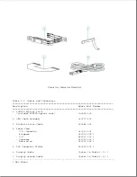
- Display cable
- Display latches
- Display clutches
- Display enclosure
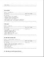
4.10 Keyboard
4.11 Diskette drive and cable
4.12 Hard drive
- Hard drive security clips
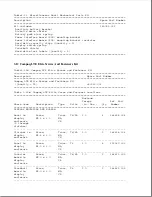
4.13 Processor board
4.14 Power interface board (PIB)
4.15 PCMCIA ejector rails
4.16 Internal AC power supply
4.17 System board and I/O bracket
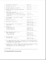
4.18 LED cable assembly
4.19 Computer base enclosure
4.20 PCMCIA compartment door
4.21 Battery pack/hard drive release latch assemblies
4.4 Preparation Procedures For Removal And Replacement
Before beginning removal and replacement procedures, complete the following
steps:
1. Read and observe the precautions in Section 4.1.
2. Turn off the computer.
3. Undock the computer if it is docked in an expansion base or a
convenience base (refer to Appendix D, "Docking and Undocking").
4. Disconnect the power cord.
5. Remove the battery pack (Section 4.5).
6. Remove any installed diskette.
7. Remove PCMCIA cards.
>>>>>>>>>>>>>>>>>>>>>>>>>>>>>>>>> CAUTION <<<<<<<<<<<<<<<<<<<<<<<<<<<<<<<<<
To prevent damage to the system unit or the peripheral devices, ensure that
the system unit power is off before connecting or disconnecting cables.
>>>>>>>>>>>>>>>>>>>>>>>>>>>>>>>>>>>>><<<<<<<<<<<<<<<<<<<<<<<<<<<<<<<<<<<<<<
8. Turn off all external devices, then disconnect them from the computer.
9. Close the display.
>>>>>>>>>>>>>>>>>>>>>>>>>>>>>>>>> CAUTION <<<<<<<<<<<<<<<<<<<<<<<<<<<<<<<<<
Electrostatic discharge (ESD) can damage electronic components. Be sure
that you are properly grounded before performing the following procedures.
Summary of Contents for LTE Elite
Page 140: ...7 Remove the hard drive security clips by gently lifting up on them Figure 4 32 ...
Page 248: ...4 Remove the keylock from the outside of the bottom cover Figure 9 5 ...
Page 249: ...5 Slide the plastic keylock barrel out of the bottom cover Figure 9 6 ...
Page 269: ...3 Disconnect the harness extension cable from the system board Figure 9 26 ...
Page 297: ...5 Slide the switch board out of the switch frame Figure 9 52 ...
Page 304: ...5 Replace the eject switch and screw Figure 9 59 ...
Page 309: ...5 Replace the power switch and screw Figure 9 64 ...
Page 348: ...7 Unlock the expansion base keylock Figure D 3 ...
Page 369: ...9 Push the lever toward the back of the convenience base Figure D 16 ...
Page 373: ...5 Slide the computer toward you to remove it from the convenience base ...
Page 387: ......

