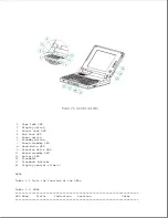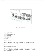
o Numeric keypad connector
o Speaker and speaker amplifier
o Power switch
o Standby button
o Display switch
o The following LEDs:
- Power/standby
- Scroll lock
- Caps lock
- Num lock
Refer to Section 1.4 for more information on the controls and LEDs listed
above.
Memory Expansion Board
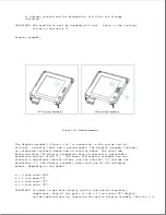
The 4 or 8 MB base RAM memory (depending on the model) may be increased by
adding an optional memory expansion board (Figure 1-9). The memory
expansion board plugs directly into the back side of the system board
(Section 4.6).
The system supports the following 3.3 volt memory expansion boards (which
operate at 70ns):
Summary of Contents for LTE Elite
Page 140: ...7 Remove the hard drive security clips by gently lifting up on them Figure 4 32 ...
Page 248: ...4 Remove the keylock from the outside of the bottom cover Figure 9 5 ...
Page 249: ...5 Slide the plastic keylock barrel out of the bottom cover Figure 9 6 ...
Page 269: ...3 Disconnect the harness extension cable from the system board Figure 9 26 ...
Page 297: ...5 Slide the switch board out of the switch frame Figure 9 52 ...
Page 304: ...5 Replace the eject switch and screw Figure 9 59 ...
Page 309: ...5 Replace the power switch and screw Figure 9 64 ...
Page 348: ...7 Unlock the expansion base keylock Figure D 3 ...
Page 369: ...9 Push the lever toward the back of the convenience base Figure D 16 ...
Page 373: ...5 Slide the computer toward you to remove it from the convenience base ...
Page 387: ......


