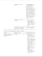
is not attached or is
contacts board is
damaged.
attached properly to
the expansion base
system board.
2. Ensure that none of
the wires on the
battery contacts board
cable are damaged or
disconnected from the
rest of the cable. If
they are damaged or
disconnected, replace
the battery contacts
board. Route the cable
properly to ensure
that damage does not
reoccur (Section
9.14).
--------------------------------------------------
The battery contacts are
1. Ensure that all
damaged.
battery contacts
are straight.
2. Replace the battery
contacts board and
route the wires
properly (Section
9.14).
--------------------------------------------------
The expansion base system
Replace the expansion
board battery charging
base system board.
circuitry is defective.
===========================================================================
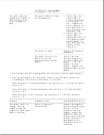
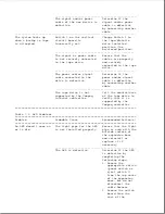
Table 7-2a. Docking/Undocking Problems (Docking)
===========================================================================
Problem
Probable Cause
Recommended Action(s)
===========================================================================
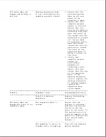
The motor does not
No power.
1. Ensure that the
engage and no beep is
power cord is
emitted.
properly connected
to the expansion
base.
2. Verify that the fan
is on and that the
VBatt1 and VBatt2
outputs from the
power supply are in
specification
(Section 10.2). If
the fan is not on
or the VBatt
outputs are out of
specification,
replace the power
supply.
3. Verify that the
power supply
connector has a
tight connection to
the vertical
Summary of Contents for LTE Elite
Page 140: ...7 Remove the hard drive security clips by gently lifting up on them Figure 4 32 ...
Page 248: ...4 Remove the keylock from the outside of the bottom cover Figure 9 5 ...
Page 249: ...5 Slide the plastic keylock barrel out of the bottom cover Figure 9 6 ...
Page 269: ...3 Disconnect the harness extension cable from the system board Figure 9 26 ...
Page 297: ...5 Slide the switch board out of the switch frame Figure 9 52 ...
Page 304: ...5 Replace the eject switch and screw Figure 9 59 ...
Page 309: ...5 Replace the power switch and screw Figure 9 64 ...
Page 348: ...7 Unlock the expansion base keylock Figure D 3 ...
Page 369: ...9 Push the lever toward the back of the convenience base Figure D 16 ...
Page 373: ...5 Slide the computer toward you to remove it from the convenience base ...
Page 387: ......


