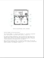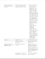
sensor is aligned
straight over its
holes in the
expansion base
system board.
3. Replace the
expansion base
system board.
---------------------------------------------------------------------------
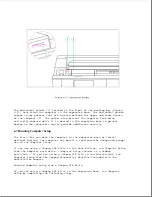
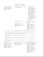
*** When verifying whether the top cover is bowed up, note that the
computer should ride on the outer edges of the docking bay of the
expansion base and not in the center area. If the center area has
scuff marks or if the computer can rock from side to side while in the
docking bay, this indicates that the top cover is bowed up.
**** Compaq LTE Lite must use the SmartStation Adapter to dock in the
Compaq SmartStation (Section D.1).
===========================================================================
Problem
Probable Cause
Recommended Action(s)
===========================================================================
The motor engages,
A foreign object is
Ensure that there is
but the docking
interfering.
no foreign object
mechanism doesn't
between the
pull the computer
computer and the
towards the expansion
expansion base.
base.
--------------------------------------------------
The top cover is bowing
Check for bowing in
up.
the top cover. *** If
bowed, complete the
following steps as
required:
1. Ensure that the
drive cage spacer
is installed
properly (Section
9.16). Reinstall
the spacer if
improperly
installed or
missing.
2. Replace the top
cover.
--------------------------------------------------
The docking mechanism
1. Ensure that the
sled is defective.
docking mechanism
sled is functioning
properly.
2. Replace the docking
mechanism.
===========================================================================
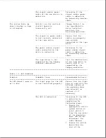
Table 7-2b. Docking/Undocking Problems (Undocking)
===========================================================================
Problem
Probable Cause
Recommended Action(s)
===========================================================================
The motor does not
No power.
1. Ensure that the
engage, and no beeps
power cord is
are emitted.
properly connected
to the expansion
Summary of Contents for LTE Elite
Page 140: ...7 Remove the hard drive security clips by gently lifting up on them Figure 4 32 ...
Page 248: ...4 Remove the keylock from the outside of the bottom cover Figure 9 5 ...
Page 249: ...5 Slide the plastic keylock barrel out of the bottom cover Figure 9 6 ...
Page 269: ...3 Disconnect the harness extension cable from the system board Figure 9 26 ...
Page 297: ...5 Slide the switch board out of the switch frame Figure 9 52 ...
Page 304: ...5 Replace the eject switch and screw Figure 9 59 ...
Page 309: ...5 Replace the power switch and screw Figure 9 64 ...
Page 348: ...7 Unlock the expansion base keylock Figure D 3 ...
Page 369: ...9 Push the lever toward the back of the convenience base Figure D 16 ...
Page 373: ...5 Slide the computer toward you to remove it from the convenience base ...
Page 387: ......

