background image

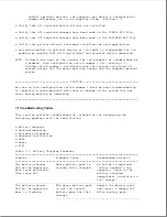
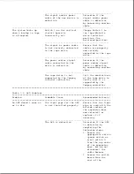
are proper. ** If the
outputs are not
proper, replace the
expansion base system
board.

---------------------------------------------------------------------------
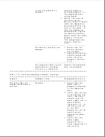
The motor starts to

There is a physical

Undock the computer

engage, but the

obstruction.

by pressing the eject

computer does not

button. If the

completely undock and

computer does not

a beep is emitted.

undock, remove the
computer using the
manual eject override
method (Section D.1),
and complete the
following steps as
required:
1. Check that the

docking mechanism
sled can move
freely back and
forth. If there is
resistance, make
sure that the sled
is clean and free
of foreign
substances.

2. Ensure that the

bottom of the
computer and the
surface of the
expansion base
docking bay are
clean.

3. Ensure that the

rubber feet are
properly located
on the bottom of
the computer.

4. Gently shake the

expansion base
upside down and
listen for any
loose objects.

---------------------------------------------------------------------------
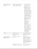
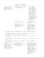
** The voltage outputs for the motor cable's red and white wires vary

according to the state of the motor, as follows:

When the motor is turning forward, the red wire is + 18V and the white
wire is 0V.

When the motor is turning backward, the red wire is 0V and the white
wire is + 18V.

When the motor is not turning, the red wire is + 18V and the white
wire is + 18.

===========================================================================
Problem

Probable Cause

Recommended Action(s)

===========================================================================

The top cover is bowing

Check for bowing in

Summary of Contents for LTE Elite

Page 1: ...ved Printed in the U S A Compaq Deskpro LTE Contura Registered U S Patent and Trademark Office LTE Elite SmartStation and MiniStation are trademarks of Compaq Computer Corporation Microsoft and MS DOS are registered trademarks of Microsoft Corporation Windows is a trademark of Microsoft Corporation The software described in this guide is furnished under a license agreement or nondisclosure agreeme...

Page 2: ...action is represented by the key names and the plus symbol For example Ctrl Alt Delete o The names of files are presented in uppercase as shown here FILENAME o The names of commands or directories are presented in uppercase type as shown here COMMAND or DIRECTORY Commands that are to be entered at the system prompt are shown on a separate line o When you are asked to type something without pressin...

Page 3: ...expansion base allow at least 3 inches 7 62 cm of clearance at the back and sides of the units To avoid the risk of electric shock or damage to the computer or expansion base ensure that all power sources including the battery pack in the computer are disconnected before removing and replacing internal parts Compaq SmartStation The Compaq SmartStation expansion base is designed for connection to a...

Page 4: ... o Models and features o Controls and LEDs o Connectors o Functional descriptions o Docking options o Running Computer Setup o Reprogrammable flash ROM o Power Management o Security 1 1 Serial Number The computer serial number should be provided to Compaq whenever requesting information or ordering spare parts The serial number is located above the connectors behind the input output I O connector ...

Page 5: ...de Adapter o Compaq MiniStation EN or Compaq MiniStation TR When docked in one of these options the computer has the following additional features o A single connection that provides multiple pass through connections to options such as a printer monitor and other external equipment o Built in network and SCSI 2 capability on the Compaq SmartStation and Compaq MiniStations only o Two internal drive...

Page 6: ...pack o The computer s internal AC adapter when connected to the power cord Figure 1 2 o The computer s internal AC adapter when docked in a convenience base o The 198 pin external options connector when docked in an expansion base provides DC power o Automobile Adapter provides DC power ...

Page 7: ...Processor Cache RAM Hard Drive 4 75CX 9 5 Color TFT 486 DX4 75 MHz 16 KB 8 MB 340 or 510 MB 4 50CX 9 5 Color TFT 486 DX2 50 MHz 8 KB 8 MB 340 MB 4 40CX 8 4 Color TFT 486 DX2 40 MHz 8 KB 4 MB 170 or 340 MB 4 50E 9 5 Mono TFT 486 DX2 50 MHz 8 KB 4 MB 250 MB 4 40C 9 5 Color STN 486 DX2 40 MHz 8 KB 4 MB 170 MB Features All models of the computer have the following features ...

Page 8: ...compatible keyboard Enhanced III type with 12 function keys o External keyboard mouse support o External numeric keypad support o Enhanced parallel port EPP 1 9 o PCMCIA slot capable of handling one of the following card combinations Two PCMCIA Type I or Type II cards One PCMCIA Type III card o Nickel metal hydride NiMH battery pack o Battery power management features including the following Four ...

Page 9: ...ntation Plug and Play BIOS MS DOS and Windows based shutdown capability for closing out applications and turning off computer Microsoft Video for Windows Runtime Version Adaptec 6360 SCSI drivers Universal Netware Client for simplified setup of a Netware network Intel Ethernet drivers and TI Token Ring drivers for networks other than Netware Western Digital WIN graphics drivers Logitech Trackball ...

Page 10: ...tch 6 Standby button 7 Power standby LED 8 Hard drive LED 9 Diskette drive LED 10 Power standby LED 11 Battery LED 12 Trackball 13 Trackball buttons 14 Display control slide s LEDs Table 1 2 lists the function of the LEDs Table 1 2 LEDs LED Name Status Indication Location Color ...

Page 11: ...selected Num Lock On Num lock Top of unit Green selected Display Switch The computer has a display switch mounted on the power interface board PIB located near the display hinge When the display is closed this switch activates the front mounted power standby LED and simultaneously deactivates the display and the top mounted LEDs Trackball The computer has an integrated PS 2 style trackball located...

Page 12: ... the convenience base and the convenience base is turned on AC power is applied to the computer s AC power connector The 198 pin connector carries all other signals between the two units Automobile Adapter Connector The computer has an automobile adapter connector that accepts an 18 5 volt 1 73 amp DC input from the Automobile Adapter This connector is covered by an access door Figure 1 5 ...

Page 13: ...o not attempt to defeat this protective feature of the door or internal damage to the computer may result Serial Connector The serial connector supports the serial interface which meets EIA RS232C specifications 198 Pin External Options Connector The 198 pin external options connector handles the signal interface between the computer and the expansion base or convenience base NOTE When connected t...

Page 14: ...m resolution of 1024 x 768 lines NOTE The computer can simultaneously display on an external monitor and the integrated display panel Numeric Keypad Connecting the numeric keypad connector to an external numeric keypad disables the embedded numeric keypad feature PCMCIA Connector The computer has a PCMCIA connector accessible through a PCMCIA slot on the left side of the computer refer to PCMCIA S...

Page 15: ...o board connection to the following devices Power interface board PIB 3 Processor board 4 Memory expansion board on underside of system board o Cable connection to the following devices Internal AC power supply board 5 Fan 6 Internal keyboard 7 Display 8 Diskette drive 9 LED cable assembly for front mounted LEDs on underside of system board ...

Page 16: ... management interrupt SMI support logic Power management features o Peripheral controller which provides the following Integrated keyboard controller Industry Standard Architecture ISA support logic Circuit for interfacing to the hard drive Control of parallel and serial interfaces including serial interfaces for a numeric keypad mouse keyboard and internal trackball o PCMCIA controller o Local bu...

Page 17: ... replaced Processor Board The SL Enhanced Intel486 processor has an integrated coprocessor and is upgradeable by replacing the processor board Figure 1 7 The system automatically adjusts to the new configuration In addition the processor board contains the primary temperature sensor refer to Temperature Sensors Some models have a heat sink attached The computer comes with one of the following proc...

Page 18: ...ent interrupt SMI is generated that creates a pop up window depicting a thermometer to warn the user of the temperature overload and the unit goes into Standby within several seconds If the temperature continues to rise the computer turns itself off NOTE The temperature sensors are integrated into the processor board and the system board To replace a temperature sensor the appropriate board must b...

Page 19: ...1 4 for more information on the controls and LEDs listed above Memory Expansion Board The 4 or 8 MB base RAM memory depending on the model may be increased by adding an optional memory expansion board Figure 1 9 The memory expansion board plugs directly into the back side of the system board Section 4 6 The system supports the following 3 3 volt memory expansion boards which operate at 70ns ...

Page 20: ... Use only Compaq LTE Elite memory expansion boards Table 3 2 Refer to the table in Section 5 3 for a list of total RAM memory based on available system memory and memory obtained from the expansion board Internal AC Power Supply AC to DC The computer is powered by a high efficiency board mounted internal AC to DC power supply Figure 1 10 The power supply provides the computer with an 18 5 volt DC ...

Page 21: ...tem approaches maximum reliable operating temperatures refer to Temperature Sensors in this section The fan is integrated into the input output I O bracket fan assembly To replace the fan the I O bracket fan assembly must be replaced CAUTION To properly ventilate the computer allow at least a 3 inch 7 62 cm clearance at the back and sides of the unit Keyboard The internal keyboard is connected to ...

Page 22: ...y conditioning the battery pack and disposal of a used battery pack WARNING Do not crush puncture or incinerate the battery pack or short the battery pack external contacts Do not open a battery pack as this damages the pack makes it unusable and exposes potentially harmful battery components There are no field serviceable parts located inside the battery pack Auxiliary Battery The internal auxili...

Page 23: ...arts located inside the battery CAUTION If the computer is unused for approximately 60 days without being connected to an external power source a fully charged auxiliary battery will drain to a critically low level This may result in loss of alarm time and date information If this happens recharge the auxiliary battery or replace it if it is defective refer to Section 4 8 Run Computer Setup to res...

Page 24: ...on 4 12 When the security clips are installed a lock label should be attached to the front of the hard drive to indicate that the drive is locked in place The computer must be partially disassembled to remove the security clips before the hard drive can be removed NOTE The Compaq Diagnostics utilities which include Computer Setup reside in a hidden partition on the Compaq LTE Elite hard drive not ...

Page 25: ...nd black and white TFT display assemblies have an externally adjustable brightness control slide 1 The color STN display assembly has two externally adjustable control slides one for contrast 2 and one for brightness 3 The display assembly comes with one of the following panels depending on the model o 9 5 inch color STN o 9 5 inch mono TFT o 8 4 inch color TFT o 9 5 inch color TFT IMPORTANT In or...

Page 26: ...m board The connector is accessible through the PCMCIA slot 1 Figure 1 15 which is covered by a PCMCIA compartment door The slot accommodates one of the following card combinations o Two PCMCIA Type I or Type II cards o One PCMCIA Type III card The PCMCIA slot supports both 5 volt and 3 3 volt PCMCIA cards in accordance with PC Card Standard Release 2 1 or later and the Exchangeable Card Architect...

Page 27: ... To ensure compatibility select a Compaq PCMCIA modem or other vendor cards on the tested list Call Compaq Reseller Support to have a copy of the list faxed to you 1 7 Docking Options The Compaq LTE Elite docks with the following options Figure 1 16 o Compaq SmartStation expansion base o Compaq LTE Lite Desktop Expansion Base with an Upgrade Adapter o Compaq MiniStation EN and MiniStation TR conve...

Page 28: ...4 Select Computer Setup from the Configuration and Diagnostics menu 5 Follow the instructions on the screen 1 9 Reprogrammable Flash ROM The flash ROM can be reprogrammed to update system firmware and provide the most recent level of system functionality In some cases problems may be solved by upgrading the ROM Erase and reprogram the nonvolatile read only memory ROM by using the ROMPaq utility Th...

Page 29: ...omponents A timeout is specified period of system or component inactivity After this period the system or component for example the hard drive is shut down to conserve power until it is accessed again If the power conservation rate and timeouts are not selected the computer uses the default settings listed in Table 1 3 Table 1 3 Power Conservation Default Settings Battery Power AC Power Feature De...

Page 30: ... if this option is preselected When the user exits Standby by pressing the standby button again information returns to the screen at the point where Standby was initiated Under battery power the computer can maintain Standby for up to 120 hours NOTE The computer cannot initiate Standby under the conditions listed above when docked in an expansion base or a convenience base In addition the computer...

Page 31: ...w battery level if preselected o Manually by simultaneously pressing the Fn key and standby button When the computer is turned on again the system exits Hibernation and the user is returned to the previous place in the application from the hard drive NOTE Hibernation cannot be initiated when the computer is in an expansion base or a convenience base Battery Operating Time Battery operating time is...

Page 32: ... unauthorized access o Provision for an optional cable lock Figure 1 18 to lock the computer to an immovable object NOTE For procedures to clear the power on password refer to Clearing the Power On Password in Section 2 1 NOTE The cable lock Kensington MicroSaver Security System Model 64068 Figure 1 19 is available from Kensington Microwave Limited or major computer resellers worldwide at 1 415 57...

Page 33: ...mplete the remaining recommended actions NOTE If the problem was intermittent check the unit several times to verify that the problem is solved Refer to Chapter 4 for any removal and replacement procedures that are recommended 2 1 Preliminary Steps IMPORANT Use AC power when running POST Computer Setup and Computer Checkup A low battery condition could initiate Standby and interrupt the program Be...

Page 34: ... on password clears CMOS the EEPROM that contains configuration information for all external devices the setup password and all other security features including o QuickLock o QuickBlank o Diskette drive disable o Diskette boot ability disable o Serial port disable o Parallel port disable o PCMCIA slot disable NOTE Disconnecting the auxiliary battery does not clear the power on password If the pas...

Page 35: ...the battery pack IMPORTANT Ensure that the battery pack is charged since a low battery condition could initiate Standby and interrupt the procedure 8 Turn on the computer The ROM clears the power on password during POST 9 After POST finishes turn off the computer 10 Remove the battery pack 11 Move the jumper back to the normal 1 2 position ...

Page 36: ...elf Test POST The Power On Self Test POST is a series of diagnostic tests that run automatically when the system is turned on POST detects which types of mass storage devices are installed in the computer and checks that the following assemblies are functioning properly o Diskette drive o Display o External keyboard o Hard drive o Internal keyboard controller o Memory expansion board o Processor b...

Page 37: ... lists visual error messages for POST audible beep error messages probable causes and recommended actions Table 2 1 Power On Self Test Messages Message Beeps Probable Cause Recommended Action 101 ROM Error 1 Long System ROM checksum 1 Inspect the ROM 1 Short invalid placement 2 Replace the ROM 3 Flash the ROM 4 Replace the system board 101 I 0 ROM None Option ROM checksum 1 Inspect the ROM Error i...

Page 38: ... configures to the default settings if you do not run Computer Setup Message Beeps Probable Cause Recommended Action 201 Memory None RAM failure 1 Make sure the memory Error module is installed correctly 2 Clean the contacts of the memory module and system board 3 Make sure PCMCIA memory card is installed correctly by running PCMCIA card service software and Computer Setup 4 If using ISA expansion...

Page 39: ... Cause Recommended Action 303 Keyboard None System board Replace the system Controller Error keyboard board controller failure 304 Keyboard None Defective keyboard Check external keyboard or System Unit Error Defective system Replace system board board 40X Parallel 2 Short Both external Run Computer Setup Port X Address and internal ports Assignment are assigned to Conflict parallel port X 401 Pri...

Page 40: ...eck and or replace power and signal cables for external storage device Message Beeps Probable Cause Recommended Action 611 Primary 2 Short Configuration Run Computer Setup Floppy Port error Address Assignment Conflict 612 Secondary 2 Short Configuration Run Computer Setup Floppy Port error Address Assignment Conflict 702 None Coprocessor error Replace the processor Coprocessor board Detection Erro...

Page 41: ...etup Disk Port and external hard Address drive controllers Assignment are both assigned Conflict to the secondary address 1780 Disk 0 None Hard drive format 1 Run Computer Checkup Failure error 2 Replace the drive 1781 Disk 1 None Hard drive format 1 Run Computer Checkup Failure error 2 Replace the drive 1782 Disk None Hard drive 1 Run Computer Checkup Controller circuitry error 2 Replace the driv...

Page 42: ...r Checkup TEST Computer Checkup determines if the computer assemblies and options are recognized by the system and functioning properly Run Computer Checkup after installing or connecting a new assembly or option Computer Checkup is installed on the hard drive If the hard drive is not functioning you can run it from the Compaq Diagnostics diskette by inserting the diskette in Drive A before turnin...

Page 43: ...rors occur they are displayed when the testing is complete o Automatic Diagnostics This option runs an unattended maximum test of each device with minimal prompts You can choose how many times to run the tests to stop on errors or to print or file a log of errors o Prompted Diagnostics This option allows maximum control over the device testing process You can choose attended or unattended testing ...

Page 44: ... Specific problem Table 2 2 Processor Computer Checkup Error Codes Error Code Description Recommended Action 101 xx CPU test failed Replace the processor board 102 xx Coprocessor error Replace the processor board 103 xx DMA page registers Replace the system board test failed 104 xx Interrupt controller Replace the system board master test failed 105 xx Port 61 error Replace the system board 106 xx...

Page 45: ...apply to failed 201 xx through 202 xx error codes 202 xx Memory system ROM checksum failed 1 Replace the system ROM 2 Replace the memory expansion board 3 Replace the system board 203 xx Memory write read The following steps apply to test failed 203 xx through 210 xx error codes 204 xx Memory address test failed If you don t have a memory expansion board replace the 206 xx Increment pattern proces...

Page 46: ...em board Table 2 5 Parallel Printer Computer Checkup Error Codes Error Code Description Recommended Action 401 xx Printer failed or not The following steps apply to connected 401 xx through 498 xx error codes 402 xx Printer data register failed 1 Connect the printer 2 Check power to the printer 403 xx Printer pattern test 3 Install the loopback connector failed 4 Replace the system board 498 xx Pr...

Page 47: ...able 2 7 Serial Computer Checkup Error Codes Error Code Description Recommended Action 1101 xx Serial port test Replace the system board Table 2 8 Modem Communications Computer Checkup Error Codes Error Code Description Recommended Action 1201 xx Modem internal The following steps apply to loopback test 1201 xx through 1210 xx error codes 1202 xx Modem timeout test 1 Refer to modem documentation 1...

Page 48: ...write read compare 4 Replace the system board test failed 1704 xx Hard drive random seek test failed 1705 xx Hard drive controller test failed 1706 xx Hard drive ready test failed 1707 xx Hard drive recalibration test failed 1708 xx Hard drive format bad track test failed 1709 xx Hard drive reset controller test failed 1710 xx Hard drive park head test failed 1714 xx Hard drive file write test fai...

Page 49: ... the system board 1905 xx Tape read test failed 1906 xx Tape write read compare test failed Table 2 11 Video Computer Checkup Error Codes Error Code Description Recommended Action 2402 xx Video memory test The following step applies to failed 2402 xx through 2480 xx error codes 2403 xx Video attribute test failed Replace the system board 2404 xx Video character set test failed 2405 xx Video 80 x 2...

Page 50: ...2423 xx ECG VGC 640 x 350 64 color set test failed Replace the system board 2424 xx ECG VGC monochrome text mode test failed 2425 xx ECG VGC monochrome graphics mode test failed 2431 xx 640 x 480 graphics The following step applies to test failure 2402 xx through 2480 xx error codes 2432 xx 320 x 200 graphics 256 color mode test Replace the system board failure 2448 xx Advanced VGA controller test...

Page 51: ...to the network controller s and retest 4 Ensure that any jumpers or DIP switches on the controller board are set to the correct positions Refer to the hardware documentation for more information 5 If the network controller is a stand alone board replace the board 6 If the network controller is integrated into the expansion base system board replace the expansion base system board 7 If using multip...

Page 52: ...028 xx and 6029 xx error codes 6029 xx Ethernet external loopback test failed 1 If using external loopback plug s check that the correct type of loopback plug is being used 2 If using external loopback plugs check that loopback plug is connected to the correct media connector at the rear of the computer 3 If using a live network for this test ensure that the network concentrators and cables are fu...

Page 53: ...efer to recommended actions for loopback test failed Error Code 6028 xx 6069 xx Token Ring external Refer to recommended actions for loopback test failed Error Code 6029 xx 6089 xx Token Ring open Refer to recommended actions for Error Code 6029 xx MAU Multi station Access Unit UTP STP Unshielded Twisted Pair Shielded Twisted Pair SCSI Computer Checkup Error Codes The SCSI Computer Checkup error c...

Page 54: ...x ID xx05 xx Read xx06 xx SA Media xx23 xx Random Read Table 2 14C SCSI Computer Checkup Error Codes SCSI Test Error Codes Error Code Description Recommended Action xxxx 02 Drive not installed Check cable connections xxxx 03 Media not in drive Check for and install DATA CD or write enabled tape in drive xxxx 05 Seek failure Replace the indicated device xxxx 06 Drive timed out Replace the indicated...

Page 55: ...drive Replace the indicated device disconnected xxxx 33 Illegal controller Replace the indicated device command xxxx 34 Invalid SCSI bus phase Replace the indicated device xxxx 35 Invalid SCSI bus phase Replace the indicated device xxxx 36 Invalid SCSI bus phase Replace the indicated device xxxx 39 Error status from drive Replace the indicated device xxxx 40 Target timed out Replace the indicated ...

Page 56: ...o display shield Place capton tape on bottom of board 6 Replace trackball 7 Replace display cable 8 Replace system board 2 4 Troubleshooting Without Error Messages This section contains troubleshooting tables that provide a quick reference for diagnosing problems that cannot be identified by running POST or Computer Checkup such as a non functional display that does not allow viewing error message...

Page 57: ...hat all required changes have been made to the CONFIG SYS file o Verify that all required changes have been made to the AUTOEXEC BAT file o Verify that printer drivers have been installed for each application Table 2 16 Battery Problems Problem Probable Cause Solution s Battery LED Low battery beeps were Use Power Management to turn flashes to turned off on the low battery warning indicate low bee...

Page 58: ...wn and data replaced within one wait until the power standby was lost when minute when the light is flashing and replacing the computer was in Standby remove the battery pack battery pack Insert a charged battery pack within one minute Auxiliary battery charge Recharge the auxiliary is low or the auxiliary battery battery is at end of its life Replace the auxiliary battery Every time the Auxiliary...

Page 59: ... Cause Solution s Battery gauge If battery pack is new Fully charge the battery displays a question mark is pack until the battery LED question mark displayed until battery turns off If problem pack is fully charged still exists complete the following steps 1 Allow the battery pack to cool off 2 Partially discharge the battery pack 3 Fully recharge the battery pack The battery pack has Fully charg...

Page 60: ... wrong type of Use the type of diskette cannot read a diskette is being used required by the drive diskette Diskette has a bad Copy files to the hard drive sector or another diskette Reformat or replace the bad diskette Drive error has Run Computer Checkup occurred Diskette is not Format the diskette formatted Table 2 19 Display Problems Problem Probable Cause Solution s Characters are Control sli...

Page 61: ... LED is flashing Problem Probable Cause Solution s Screen is blank System has entered a If available immediately the power standby low battery Standby connect the computer to an LED is flashing condition The computer external power source or and the battery will next activate insert a charged battery LED is flashing Hibernation if this pack Then press the standby feature is not disabled button to ...

Page 62: ...back to resolution computer is internal display which connected to only supports 640 X 480 external monitor resolution Problem Probable Cause Solution s Internal display External monitor was Turn the computer off and and external connected after the connect the external monitor do not computer was turned on monitor Turn the external display monitor on then turn on the information computer simultan...

Page 63: ...olution s Backlight Power Management Verify that you have not brightness settings are set high selected a Power Management cannot be causing a dim display setting that limits the adjusted with the output of the backlight brightness control slide Control slide is seated Remove the control slide improperly from the display bezel and reseat it Improper display cable 1 Reseat the display cable connect...

Page 64: ...Display board single color on 3 Inverter board it or has garbled graphics across the entire panel This failure is for patterns across the entire panel not just on one section Defective display cable Replace the display cable Defective inverter Replace the inverter board board on color STN models only Defective system board Replace the system board A single line Defective display panel Replace the ...

Page 65: ...the LEDs to turn on at the front of the computer The spare display panel inverter board display cable and display enclosure for the 9 5 color TFT models come preinstalled in a display assembly To replace these parts on the 9 5 inch color TFT models replace the entire display assembly The brightness adjustment function on TFT panels must be tested with the display bezel on since these panels contai...

Page 66: ...previously unusually long battery condition and saved data to its exact time after is now exiting from it state before Hibernation restarting the computer Hard drive error Hard drive has bad Run Computer Checkup occurs sectors or has failed Hard drive does Hard drive is not seated Turn off and unplug the not work properly computer remove the battery pack and remove and then reinsert the hard drive...

Page 67: ...ter or is correctly configured incorrectly 2 Run Computer Setup Out of Memory Too many TSRs are Delete any TSR applications message is installed that are not needed displayed on the screen or insufficient memory error occurs during operation Memory configuration is Reconfigure the memory using not set up correctly MS DOS MEMMAKER System ran out of memory 1 Check the application for the application...

Page 68: ... A file from the Network Install diskette must be installed when using the Compaq LTE Elite with certain network adapters while in certain operating environments The Network Install diskette is included with the Compaq SmartStation and the Compaq LTE Lite Desktop Expansion Base Upgrade Kit The README DOC file on the diskette details how to use each file and specifies the network interface cards an...

Page 69: ...nector on the on the expansion base expansion base There is a problem with Ensure that the cable and the cable or a device at device at the other end of the other end of the the network connection are cable operating properly There is a hardware Replace the expansion base failure in the expansion system board base Computer Checkup The network drivers are Ensure that the network TEST reports no not...

Page 70: ...e network application has slow performance or the network application loses the network connection Table 2 25 PCMCIA Problems Problem Probable Cause Solution s When turned on Card is not inserted Remove and reinsert the card the computer does properly in the correct orientation not beep when a PCMCIA card is inserted PCMCIA beeps are From MS DOS Run the PCCARD disabled utility to reenable PCMCIA b...

Page 71: ... messages the PCMCIA slot when the computer is turned on From Windows environment Select Security Management from the Compaq Control Center to enable the PCMCIA slot PCMCIA modem or Wrong COM port being From MS DOS Run CARDINFO to fax card does not used to access the card determine which COM port is work assigned to the card From Windows Select Computer Setup from the Compaq Control Center to dete...

Page 72: ...lect Computer Setup from storage cards require the Compaq Control Center the PCMCIA ATA driver to then select the PCMCIA be loaded option to enable the PCMCIA ATA driver You are trying to access From MS DOS Run CARDINFO to the card using the wrong determine which drive letter drive letter is assigned to the card From Windows Select Computer Setup from the Compaq Control Center to see which drive l...

Page 73: ...ngly hot environment Let the computer cool down Fan may be blocked Make sure airflow at rear causing temperature to and sides of computer is not exceed limits obstructed Computer turned System initiated Turn on the computer off while left Hibernation according to unattended Power Power Management LED is off settings System initiated Install a fully charged Hibernation due to a battery pack or conn...

Page 74: ...e following battery LED are off 1 Remove keyboard cover and verify that the If the other LEDs power switch small come for any button on power period of time interface board moves even for a freely If it binds or is momentary flash damaged replace the this is not a keyboard cover no power problem 2 Try to operate the power switch with the keyboard cover removed If the unit will not power up or down...

Page 75: ...ime until the short circuit is located a Disconnect the display cable from the inverter board and attempt to power the unit up If the unit powers up replace the inverter board b Disconnect the display cable from the trackball board and power the unit up If the unit powers up replace the trackball board c Disconnect the display cable from the display panel and power the unit up If the unit powers u...

Page 76: ...place the cable long unshielded or defective If you experience problems printing run a printer self test to determine if it is a printer specific problem Refer to the documentation provided with the printer and the application software Table 2 28 Software Application Problems Problem Probable Cause Solution s Cannot use an The application has not 1 Add or edit the application been added to the PAT...

Page 77: ...Power off Management utility Section 1 10 Table 2 30 Standby Problems Problem Probable Cause Solution s The standby Defective keyboard Remove the keyboard cover button is cover Press the Standby button pressed but the located on the power unit does not go interface board If problem into standby is solved install a new keyboard cover Defective power Replace the power interface interface board board...

Page 78: ...l or Mouse device driver is Enter MOUSE at the system mouse does not not activated loaded prompt to activate the mouse work even though into memory in MS DOS device driver the device driver is in the PATH command of the AUTOEXEC BAT file Add a line in the AUTOEXEC BAT file to automatically activate the mouse device driver each time the computer is turned on or restarted Display cable not Reseat ca...

Page 79: ...te o Conditions under which the problem occurred o Any error messages that have occurred o Hardware configuration o Type of printer connected o Hardware software being used o Printed results of Computer Checkup TEST and View System Information INSPECT if possible o Printed copies of CONFIG SYS and AUTOEXEC BAT files if possible Shipping Preparation To ship the computer complete the following steps...

Page 80: ...d that there are no PCMCIA cards in the PCMCIA slot 4 Close the display and all exterior doors external options PCMCIA compartment memory and hard drive 5 Pack the computer with sufficient packing material to protect it Use the original packing box or similar packaging ...

Page 81: ...aq LTE Elite Family of Personal Computers including the Compaq MiniStation EN and the Compaq MiniStation TR Refer to Chapter 8 for spare part information for the Compaq SmartStation 3 1 System Unit Enclosures Table 3 1 System Unit Enclosures Description Spare Part Number 1 Keyboard Cover 149594 001 2 Input output I O Bracket 149706 001 Includes I O bracket Fan ...

Page 82: ...latch assembly button latch and spring PCMCIA compartment door and spring Automobile adapter door Hard drive compartment door 3 2 Boards Table 3 2 Boards Description Spare Part Number 1 Processor Board 486 DX4 75 MHz 194147 001 486 DX2 50 MHz 194146 001 486 DX2 40 MHz 194149 001 2 Power Interface PIB Board 194058 001 includes display switch spring ...

Page 83: ...Board 4 MB 194007 001 8 MB 149508 001 5 Memory Expansion Board 70 ns 4 MB 194188 001 8 MB 194189 001 16 MB 196799 001 6 LED Cable Assembly 149707 001 7 Trackball Board includes trackball 149597 001 8 Inverter Board Refer to Table 3 3 Not shown 3 3 Model Specific Display Parts ...

Page 84: ...149779 001 10 4 Inch Color TFT 197940 001 3 Display Panel 9 5 Inch Color TFT 149589 001 8 4 Inch Color TFT 194039 001 9 5 Inch Black and White TFT 138041 001 9 5 Inch Color STN 149736 001 10 4 Inch Color TFT 197920 001 4 Inverter Board 9 5 Inch Color TFT 149589 001 8 4 Inch Color TFT 149587 001 9 5 Inch Black and White TFT 194141 001 9 5 Inch Color STN 149735 001 10 4 Inch Color TFT 196877 001 ...

Page 85: ...anel inverter board display cable display ground cable and display enclosure for the 9 5 color TFT display come preinstalled in a display assembly to ensure compatibility and optimize the display quality The ground cable used on the 9 5 black and white TFT and the 9 5 color STN displays may be 2 inches shorter than the one used in the other models In addition the shorter ground cable may not have ...

Page 86: ...ion Spare Part Number 1 3 5 inch 1 44 MB Diskette Drive 149749 001 2 Diskette Drive Cable 149588 001 3 Removable Hard Drive 810 MB 177819 001 510 MB 194086 001 340 MB 149591 001 250 MB 149750 001 170 MB 194079 001 4 Hard Drive Carrying Case 149783 001 3 5 Batteries ...

Page 87: ...Table 3 5 Batteries Description Spare Part Number 1 NiMH Battery Pack 149599 001 2 Auxiliary Battery 149598 001 3 6 Cables And Connectors ...

Page 88: ...l 196454 001 2 LED Cable Assembly 149707 001 3 Diskette Drive Cable 149588 001 4 Power Cord U S Canadian 149710 001 European 149710 002 U K 149710 003 Japanese 149710 007 Australian 149710 008 5 ZIF Connector Slides 140069 001 6 Display Cable Refer to Table 3 3 7 Display Ground Cable Refer to Table 3 3 Not shown ...

Page 89: ...K English 149608 003 German 149608 004 French 149608 005 Italian 149608 006 Spanish 149608 007 Danish 149608 008 Norwegian 149608 009 Swedish Finnish 149608 010 Swiss 149608 011 French Canadian 149608 012 Portuguese 149608 013 Latin American 149608 016 Belgian 149608 018 Japanese 149608 019 ...

Page 90: ...ription Spare Part Number Kit includes 194158 001 Input output I O connector cover Automobile adapter door Hard drive compartment door PCMCIA compartment door PCMCIA compartment door spring Memory access cover 3 10 Miscellaneous Plastics Kit Table3 10 Miscellaneous Plastics Kit Description Spare Part Number Kit includes 194157 001 Control slides for TFT display Quantity 3 Control slides for STN di...

Page 91: ...Description Spare Part Number Compaq LTE Elite Screws and Fasteners Kit Quantity 25 149763 001 Table 3 12b Compaq LTE Elite Screw and Fastener Locations Maximum Torque Ref Part Where Used Description Type Drive in lbs Qty Number DISPLAY ENCLOSURE AND BOARDS Bezel to Screw Truss T8 SL 3 0 4 144864 004 display M2 5 x 6 0 MA enclosure CS 2 through clutches Clutches to Screw Truss T8 SL 3 0 2 144864 0...

Page 92: ...CS monitor F external options connectors at rear PIB PCMCIA Screw Truss T8 SL 2 0 2 144863 007 rails to M 2 0 x 20 5 MA system unit CS enclosure long screws Keyboard to Screw Truss T8 SL 3 0 2 144864 004 system unit M2 5 x 6 0 MA enclosure CS System board Screw Truss T8 SL 3 0 6 144864 004 to system M 2 5 x 6 0 MA unit CS enclosure PIB to Screw Truss T8 SL 2 0 3 144863 005 PCMCIA M2 0 x 6 0 MA con...

Page 93: ...er to M2 5 x 21 0 MA system unit CS enclosure on bottom Keyboard Screw Truss T8 SL 3 0 1 144864 004 cover to M2 5 x 6 0 MA system unit CS enclosure at rear Clutches to Screw Truss T8 SL 3 0 4 144864 003 system unit M2 5 x 10 0 MA enclosure CS 3 13 Tools Table 3 13 Tools ...

Page 94: ...7 001 Includes 3 Connector Removal Tool 4 Display Bezel Removal Tool 5 Loopback Plugs Not shown 3 14 Options Table 3 14 Compaq LTE Elite Options and Accessories Description Spare Part Number 1 Compaq LTE Lite Desktop Expansion Base 199027 001 Upgrade Kit includes Network Install Diskette 192307 001 ...

Page 95: ... to Table 3 3 11 Hard Drive 340 MB 198968 001 149591 001 510 MB 197628 001 194086 001 810 MB 149685 005 163420 001 Refer to Table 3 4 12 Memory Expansion Board 70 ns 4 MB 199013 001 194188 001 8 MB 199014 001 194189 001 16 MB 196806 001 196799 001 Refer to Table 3 2 13 Processor Board 486 DX4 75 MHz 194048 001 194147 001 Refer to Table 3 2 The Compaq option part number is provided in the descripti...

Page 96: ...le 3 15 Compaq MiniStation Convenience Bases Description Spare Part Number 1 Monitor Support Cover 198860 001 2 Plastics and Mechanical Parts Kit 195564 001 including 3 Top enclosure 4 Docking mechanism 5 Bottom enclosure 6 Ventilation chamber 7 Power Cord U S Canadian 149710 001 European 149710 002 U K 149710 003 Australian 149710 008 ...

Page 97: ...q MiniStation EN and the Compaq MiniStation TR each use a different overlay Both overlays are provided with the power supply board 3 16 Software Diskettes Table3 16 Software Diskettes Description Spare Part Number Compaq Diagnostics Diskette 109728 001 EZ SCSI Configuration Software Diskette 146994 001 EZ Tape 122098 001 PCMCIA Software Kit 198821 001 ROMPaq Upgrade Diskette Kit 129899 001 Portabl...

Page 98: ...sh 149709 351 Compaq MiniStation Installation Guide English 196786 001 German 196786 041 French 196786 051 Italian 196786 061 Spanish 196786 071 Swedish 196786 101 Dutch 196786 331 Compaq Service Quick Reference Guide Quantity 5 106954 001 Compaq QuickFind U S Canadian 137906 00X International other than U S Canadian Authorized Compaq Reseller Version 137907 00X End User Version 137908 00X Compaq ...

Page 99: ...r microcircuitry Use proper packaging and grounding techniques to prevent damage Refer to Appendix E for more information on ESD CAUTION Electrostatic discharge can damage electronic components Be sure that you are properly grounded before performing any maintenance and service procedures Cables Use the following precautions when handling cables to avoid irreparable damage to the cable or the comp...

Page 100: ...ses then remove the cable Figure 4 1 CAUTION A ZIF connector and its attached cable can be easily damaged Handle only the connector slide when removing or replacing a cable Never pull or twist on the cable while it is connected IMPORTANT Due to space limitations inside the system unit the display cable cannot be removed from the system board ZIF connector using the standard removal technique To re...

Page 101: ...s and software are required to service the computer o Torx T 8 screwdriver o 3 16 inch nut driver for screwlocks o Pair of needle nosed pliers o Compaq trackball removal tool Table 3 13 o Connector removal tool Table 3 13 o Display bezel removal tool Table 3 13 o Compaq diagnostics diskette NOTE Most of the screws in the computer are slotted Torx T 8 type which can be removed and replaced with a T...

Page 102: ...omplete the following steps 1 Read and observe the precautions in Section 4 1 2 Turn off the computer 3 Undock the computer if it is docked in an expansion base or a convenience base refer to Appendix D Docking and Undocking 4 Disconnect the power cord 5 Remove the battery pack Section 4 5 6 Remove any installed diskette 7 Remove PCMCIA cards CAUTION To prevent damage to the system unit or the per...

Page 103: ...n the battery compartment To prevent damage do not allow metal objects to touch the battery contacts Place only the battery pack for the Compaq LTE Elite Family of Personal Computers into the battery compartment The Compaq LTE Elite battery pack and the battery compartment are keyed to allow only a correct insertion Do not attempt to insert a battery pack for a Compaq LTE Lite computer or any othe...

Page 104: ...tment 2 Push firmly on the battery pack When released it locks into place 4 6 Memory Expansion Board Random access memory RAM can be added to the computer by installing a memory expansion board Refer to Section 1 6 and Table 3 2 for more information on RAM expansion CAUTION Electrostatic discharge ESD can damage electronic components Ensure that you are properly grounded before beginning these pro...

Page 105: ...the unit display side down 2 Release the latch on the memory access cover Figure 4 3 3 Slide the cover in the direction indicated by the embossed arrow on the cover and remove it CAUTION Do not lift on the middle of the memory expansion board or you may damage it Lift simultaneously from the connector ends of the board 4 Carefully remove the memory expansion board by lifting from the connector end...

Page 106: ...ing the correct connectors 1 Position the memory expansion board over the system board connectors ensuring that it is correctly oriented Figure 4 4 CAUTION Do not apply pressure to the middle of the memory expansion board or you may damage it Press only in the area directly over the connectors Ensure that both connectors on the memory expansion board snap into place 2 Snap the memory expansion boa...

Page 107: ...edures for Removal and Replacement To remove the keyboard cover complete the following steps 1 Turn the unit display side down 2 Remove the five screws located on the bottom and the one screw shorter than the other five located near the external options connector on the rear panel Figure 4 5 ...

Page 108: ...g the unit together turn it right side up 4 Open the display to its fully open position 5 Tilt up the back edge of the keyboard cover 1 and lift while rotating the cover toward you to release the front edge 2 Figure 4 6 ...

Page 109: ... place at the back of the computer and verify that the front edge is aligned If the seam between the computer and the keyboard cover is uneven remove the keyboard cover and realign the tabs and recesses 4 8 Auxiliary Battery Refer to Auxiliary Battery in Section 1 6 for more information on the auxiliary battery To remove the auxiliary battery complete the following steps 1 Remove the keyboard cove...

Page 110: ...battery connector 2 Figure 4 7 4 Remove the auxiliary battery from its bracket Figure 4 7 NOTE When the auxiliary battery is reconnected alarm time and date information must be reset by running Computer Setup Section 1 8 Password and configuration information are not lost when the auxiliary battery is disconnected 4 9 Display Assembly The display can be upgraded to the 9 5 inch color TFT model by ...

Page 111: ...splay assembly complete the following steps 1 Remove the keyboard cover Section 4 7 CAUTION The display cable and its ZIF connector on the system board can be easily damaged Do not pull or twist on the cable while it is connected To avoid bending the small posts inside the slide release each corner of the connector slide with the connector removal tool using constant light force 2 Using the connec...

Page 112: ...able 4 Remove the display ground cable 1 from the ground clip 2 on the input output I 0 bracket Figure 4 9 IMPORTANT When replacing the display ground cable loosen the screwlocks on the parallel connector at the rear of the computer Place the tip of the connector removal tool into one of the holes 3 at the bottom corners of the ground cable Figure 4 9 Pull the cable down into the ground clip by al...

Page 113: ...from disconnecting from the ground clip 5 Remove the four screws that attach the display clutches to the computer Figure 4 10 CAUTION To avoid damaging the display assembly handle it carefully Lift it from both sides with equal force 6 Remove the display assembly from the system unit Figure 4 10 ...

Page 114: ...cord and Automobile Adapter are removed from the computer before removing or replacing the display bezel If power sources are still connected to the computer when the display bezel is being removed or replaced there is the possibility of electrical shock from high voltage in the inverter board or damage to the system components Do not operate the computer with the display bezel removed It is not n...

Page 115: ...rd when replacing the display control slide s fully snap the bezel back into place before you replace the slide s Insert the slide s back into place ensuring that they are properly aligned with the controls on the inverter board 2 Remove the four screws and screw covers from the corners of the display bezel Figure 4 11 3 Pull the bezel away from the display enclosure by separating the snaps Begin ...

Page 116: ...place the display panel on the 9 5 inch color TFT model replace the entire display assembly refer to Removing the Display Assembly in this section It is not necessary to remove the display assembly from the system unit to remove the display panel To remove the display panel complete the following steps 1 Remove the display bezel refer to Display Bezel in this section 2 Disconnect the backlight cab...

Page 117: ... remove any Phillips screws on the display panel These screws hold the display panel together There are no serviceable parts located inside the display panel 3 Remove the four T 8 screws that attach the display panel to the display enclosure Figure 4 14 ...

Page 118: ...r display brightness In addition ensure that one of the mounting tabs of the display ground cable is connected beneath the display panel and is attached by the lower left display panel screw 4 Carefully lift the display panel up to provide access to the display cable connector on the left side of the panel Figure 4 15 CAUTION The display panel is fragile Handle it carefully When moving or tilting ...

Page 119: ...the cable while it is connected Lift both corners of the ZIF connector slide simultaneously with constant light force until the connector slide releases 5 Remove the display cable connector from the display panel Figure 4 16 The display panel has one of the following types of connectors o Plug and socket type for the color TFT and color STN displays 1 o ZIF type for the black and white TFT display...

Page 120: ...or and fully seat the cable 6 Lift the display panel out of the display enclosure Inverter Board WARNING Be sure that all power sources including the battery pack AC power cord and Automobile Adapter are removed from the computer before removing or replacing the inverter board If power sources are still connected to the computer when the inverter board is being removed or replaced there is the pos...

Page 121: ...move the display bezel refer to Display Bezel in this section 2 Remove the backlight cable from the inverter board Figure 4 13 3 Remove the display cable 1 from the inverter board Figure 4 17 4 Remove the two screws 2 that attach the display inverter board to the display enclosure Figure 4 17 5 Remove the inverter board Figure 4 17 IMPORTANT In order to line up the screws properly when replacing t...

Page 122: ... replacing the trackball board screws note that there is a small amount of slack available for adjustment Before tightening the screws position the trackball board so that the trackball retaining ring will be centered in the trackball opening of the display bezel If the trackball retaining ring is not centered the display bezel may interfere with removal of the trackball retaining ring If the disp...

Page 123: ...e complete the following steps 1 Remove the keyboard cover Section 4 7 2 Remove the display cable and the display ground cable from the system unit by completing steps 2 and 3 as listed in Removing the Display Assembly in this section 3 Remove the display bezel refer to Display Bezel in this section 4 Remove the display panel refer to Display Panel in this section 5 Disconnect the display cable fr...

Page 124: ...nstalling the display latches and latch buttons on the correct sides When removing the display latches and buttons keep the left and right parts separated to ease replacement It is not necessary to remove the display assembly to remove the display latches To remove the display latches complete the following steps 1 Remove the display bezel refer to Display Bezel in this section 2 Press on the reta...

Page 125: ...section NOTE Two screws that attach the bezel to the display enclosure also attach the clutches to the display enclosure IMPORTANT Before removing the two remaining clutch screws step 4 note that these screws also attach the mounting tab of the trackball shield 2 and one of the mounting tabs of the display ground cable 3 Figure 4 21 The tab for the display ground cable goes beneath the clutch The ...

Page 126: ...s beneath the clutch 4 Remove the two remaining clutch screws Figure 4 21 5 Remove the display clutches 1 from the display assembly Figure 4 21 Display Enclosure NOTE To replace the display enclosure on the 9 5 inch color TFT model replace the entire display assembly refer to Removing the Display Assembly in this section To remove the display enclosure complete the following steps 1 Remove the key...

Page 127: ...play clutches refer to Display Clutches in this section 10 Remove the trackball shield refer to Display Clutches in this section 11 Remove the display ground cable The display enclosure is all that remains NOTE When replacing the enclosure install the logo that appears on the outside Install the logo so that it has the same orientation as the textured logo that is part of the display enclosure Ens...

Page 128: ... and ZIF connector on the system board can be easily damaged Handle only the connector slide when removing the cable never pull or twist on the cable while it is connected Lift both corners of the ZIF connector slide simultaneously with constant light force until the connector slide releases 5 Release the keyboard cable ZIF connector 2 and remove the cable 3 Figure 4 23 6 Remove the keyboard Figur...

Page 129: ...or on the system board IMPORTANT Fully seat the cable before closing the ZIF connector slide Close the connector slide by simultaneously pressing on both corners When closed the insertion line on the cable should be even with the top edge of the connector slide If it is not release the connector and fully seat the cable 2 Place the keyboard toward the back of the computer approximately 7 millimete...

Page 130: ... three tabs in the middle 2 tuck underneath the plastic edge 4 Replace the two keyboard screws Figure 4 24 4 11 Diskette Drive And Cable The diskette drive cable connects to a LIF connector on the diskette drive and to a ZIF connector on the system board To remove the diskette drive and cable complete the following steps 1 Remove the keyboard cover Section 4 7 2 Remove the keyboard Section 4 10 3 ...

Page 131: ...ard can be easily damaged Handle only the connector slide when removing or replacing the cable never pull or twist on the cable while it is connected to the ZIF connector Lift both corners of the ZIF connector slide simultaneously with constant light force until the connector slide releases 5 Release the diskette drive cable ZIF connector 1 and remove the cable 2 Figure 4 25 CAUTION When replacing...

Page 132: ... The hard drive in the computer is removable from the front without requiring disassembly However if the hard drive security clips are installed the computer must be partially disassembled to remove these clips refer to Hard Drive Security Clips later in this section CAUTION To prevent damage to the hard drive and loss of information observe these precautions when handling the hard drive ...

Page 133: ...atic electricity Avoid touching the connectors o Handle the drive carefully Do not drop o When removing the hard drive immediately place the drive into the hard drive carrying case which was provided with the computer Table 3 4 o Avoid exposing the hard drive to temperature extremes o Avoid exposure to products that have magnetic fields such as monitors or speakers o Do not spray the hard drive wi...

Page 134: ...d drive release button Do not use excessive force when pressing on the hard drive release button or pulling on the hard drive handle or pull tab If the hard drive will not come out easily or if a hard drive lock label is attached to the hard drive check to see that the hard drive security clips have been removed before proceeding refer to Hard Drive Security Clips later in this section 3 Hold down...

Page 135: ...er Setup on the Compaq LTE Elite reside in a hidden partition on the hard drive not in the ROM There is no preinstalled software on a new spare hard drive When installing a new spare hard drive the hidden partition must be created the diagnostics utilities must be installed and the C partition must be formatted before restoring any data NOTE On the option kit hard drives the hidden partition is al...

Page 136: ...ition screen appears select Create Diagnostic Partition The computer creates the partition reboots the computer and installs the diagnostics software 5 Format the C partition and install other software as necessary Hard Drive Security Clips If the hard drive security clips are installed they must be removed before the hard drive can be removed 1 If the hard drive will not come out easily or if a h...

Page 137: ...t of the battery pack keeps the computer from tipping backward when accessing the hard drive security clips You may want to insert the battery pack upside down for additional protection against it touching its contacts WARNING To prevent the battery pack from falling out and being damaged or causing possible injury be sure to remove it before moving the computer or turning the computer over 3 Cove...

Page 138: ...Figure 4 30 CAUTION To avoid damage to the keyboard be careful when handling it since the keyboard cable is still connected Do not pull on the cable 5 Gently slide the keyboard toward the display to release its front edge from the computer 2 Figure 4 30 ...

Page 139: ...6 Rotate the front edge of the keyboard up and lay it face down on the cloth covered display panel Figure 4 31 ...

Page 140: ...7 Remove the hard drive security clips by gently lifting up on them Figure 4 32 ...

Page 141: ...ps are not flush the keyboard will not fit properly Note the orientation of the clips in Figure 4 32 8 If a hard drive lock label is attached to the front of the hard drive remove it NOTE If you wish to install the hard drive security clips and lock label on the replacement hard drive do so before completing steps 9 and 10 while the computer is still disassembled 9 Replace the keyboard Section 4 1...

Page 142: ...steps 1 Remove the keyboard cover Section 4 7 CAUTION To avoid damage to the processor board do not lift from the middle of the processor board or from the processor heat sink Lift simultaneously from the left corners of the processor board to remove it from the connectors beneath the board 2 Remove the processor board from the system board by simultaneously lifting from the left corners of the pr...

Page 143: ... they are keyed so that you can only insert them in the proper manner To avoid damage to the processor board and the system board be sure that you are aligning the correct connectors To avoid damage to the processor board do not press on the middle of the processor board or on the processor heat sink Press only in the area directly over the connectors Be sure that both connectors on the processor ...

Page 144: ...ack left PIB screw Figure 4 35 IMPORTANT When replacing the PIB be sure to align the display switch spring in its alignment hole before replacing the back left screw CAUTION To avoid damage to the computer base enclosure when replacing the PIB be sure to install the screws in the correct holes The three screws are different lengths two long screws and one short screw The short screw goes in the ho...

Page 145: ...he PIB be sure to line up the connector pins as they can be easily misaligned and damaged 3 Lift up on the right side of the PIB 1 to disconnect it from the connector pins on the system board 2 Figure 4 36 4 Remove the PIB insulator 3 and PIB shield 4 Figure 4 36 4 15 PCMCIA Ejector Rails Two PCMCIA ejector rails ejectors are mounted on the system board IMPORTANT Be sure there are no PCMCIA cards ...

Page 146: ... 14 3 Remove the top ejector rail by sliding it gently but firmly out of the system unit Figure 4 37 4 Repeat step 3 for the bottom ejector rail Replacing the PCMCIA Ejector Rails IMPORTANT When replacing the ejector rails be sure that the metal eject lever on the rails seats fully into the narrow slot in the PCMCIA connector If the rails are not fully seated in the slot in the connector they will...

Page 147: ... following steps 1 Slide the bottom ejector rail into position until it locks into place Figure 4 38 2 Slide the top ejector rail into position until it locks into place Figure 4 38 3 Insert the PCMCIA spacer into the rails to assist with rail alignment Figure 4 39 ...

Page 148: ...ed into the system board To replace the DC to DC power supply the system board must be replaced WARNING Be sure that all power sources including the battery pack AC power cord and Automobile Adapter are removed from the computer before removing or replacing the internal AC power supply If power sources are still connected to the computer when the internal AC power supply is being removed or replac...

Page 149: ...ernal AC power supply complete the following steps 1 Remove the keyboard cover Section 4 7 2 Remove the hinge cover from the top of the internal AC power supply by sliding it toward the front of the unit Figure 4 40 3 Remove the two screws that attach the power supply to the top of the system unit Figure 4 41 ...

Page 150: ...o screws that attach the power supply to the rear of the system unit Figure 4 42 NOTE To allow the screws to align easier when replacing the power supply replace the two rear screws before replacing the two top screws ...

Page 151: ...ble is still attached Do not attempt to fully remove the internal AC power supply until the cable is disconnected 5 Lift up the power supply to allow access to the power supply cable Figure 4 43 6 Disconnect the internal AC power supply cable Figure 4 43 7 Remove the internal AC power supply Figure 4 43 ...

Page 152: ...rd is to be installed remove the memory expansion board Section 4 6 2 Remove the hard drive Section 4 12 3 Remove the keyboard cover Section 4 7 4 If a new system board is to be installed remove the processor board Section 4 13 5 Disconnect the auxiliary battery Section 4 8 6 Remove the display assembly Section 4 9 7 Remove the keyboard Section 4 10 ...

Page 153: ...wo screws that attach the Automobile Adapter connector to the I O bracket Figure 4 44 NOTE The screws for the Automobile Adapter connector are located under the Automobile Adapter door at the left rear of the computer Figure 4 44 IMPORTANT When replacing the Automobile Adapter connector Figure 4 45 ensure that the long end of the connector 1 is next to the fan 2 and that the ferrite on the connect...

Page 154: ...computer do not use a metal tool to remove the fan connector 14 Using a non metallic tool such as the connector removal tool Table 3 13 slightly press down against the top of the fan connector 1 to release the retentive force on the connector Figure 4 46 15 Remove the fan connector 2 Figure 4 46 ...

Page 155: ...the system board to the computer base enclosure Figure 4 47 IMPORTANT To ensure proper alignment when replacing the system board replace the screw noted as 1 then replace the screw noted as 2 then replace the other four screws Figure 4 47 ...

Page 156: ...17 Carefully tilt the system board up 1 and unplug the LED cable assembly from the connector on the bottom side of the system board 2 Figure 4 48 ...

Page 157: ...e away from the system board 18 With the system board still tilted up slide the system board toward the front of the unit to release it from the I O bracket and remove the system board 19 Slightly flex the left side of the computer base enclosure toward the back of the unit 1 and remove the I O bracket 2 Figure 4 49 ...

Page 158: ... the LED Cable Assembly To remove the LED cable assembly from the computer base enclosure complete the following steps 1 Remove the system board by completing steps 1 through 17 in Section 4 17 2 Slightly flex the retaining snaps of the LED cable assembly bracket 1 up one at a time while removing the LED cable assembly 2 Figure 4 50 ...

Page 159: ... replace the LED cable assembly complete the following steps 1 Connect the LED cable assembly 1 to its connector on the system board 2 Figure 4 51 IMPORTANT Be sure that the soldered leads on the LED cable face away from the system board ...

Page 160: ...lly install the system board so that the connectors on the back of the board fit into the I O bracket Keep the front edge of the system board raised to allow access to the LED cable assembly bracket Figure 4 52 ...

Page 161: ...ble assembly bracket Figure 4 53 4 Rotate the top edge of the LED cable assembly up and press gently at the top corners 2 Figure 4 53 to snap it into the bracket IMPORTANT Both sides of the LED cable assembly must be pressed simultaneously to allow the assembly to snap into the bracket ...

Page 162: ...ve the system board and I O bracket Section 4 17 2 Remove the LED cable assembly Section 4 18 3 Remove the I O connector cover The computer base enclosure remains and includes the following items o Battery pack release latch assembly Section 4 21 o Hard drive release latch assembly Section 4 21 o PCMCIA compartment door Section 4 20 o Automobile Adapter door o Hard drive compartment door ...

Page 163: ...9 Removing the PCMCIA Compartment Door To remove the PCMCIA compartment door complete the following steps 1 Open the door CAUTION To avoid possible damage to the PCMCIA connector or cards be sure that all PCMCIA cards have been removed before removing the PCMCIA compartment door 2 Carefully flex the door near the front 1 Figure 4 54 to release the hinge from the computer base enclosure 3 Carefully...

Page 164: ...Position the door spring 1 over its retaining post 2 on the computer base enclosure Figure 4 55 2 Position the long end of the spring 3 into its slot on top of the computer base enclosure Figure 4 55 so that it stays in place NOTE The spring automatically goes into place when the door is installed and closed ...

Page 165: ...ly open position install the back hinge of the door 1 onto its post on the computer base enclosure Figure 4 56 4 Slightly flexing the door replace the front hinge of the door 2 onto its post on the computer base enclosure Figure 4 56 ...

Page 166: ...ork together as assemblies to release the battery pack and hard drive The parts for the battery pack release latch assembly located in the right side of the computer are basically the reverse a mirror image of the parts for the hard drive release latch assembly located in the left side of the computer Both assemblies work in a similar manner NOTE Both release latch assemblies come preinstalled on ...

Page 167: ...r its wide end and pulling it straight up out of its slot Figure 4 57 5 Remove the e clip 2 that holds the latch 3 in place and slide the latch up from its post Figure 4 57 6 Remove the release button 4 Figure 4 57 CAUTION To avoid damage to the computer base enclosure do not attempt to replace the latch spring unless it is necessary since the spring is firmly attached to the enclosure Leave the e...

Page 168: ... To replace the release latch assembly complete the following steps 1 Replace the release button 1 Figure 4 58 2 Replace the latch 2 by sliding the latch onto its post Figure 4 58 NOTE If the existing latch spring was left in place prior to replacing the latch move the free end of the spring slightly out of the way to allow the latch to be at the bottom of the post CAUTION To avoid damage to the c...

Page 169: ...atch Figure 4 58 4 To replace the latch spring gently slide the spring 4 down into its slot while placing its free end 5 over the triangular shaped ledge of the latch Figure 4 58 IMPORTANT Be sure that the latch and latch spring are assembled exactly as shown in Figure 4 58 to provide tension for the battery latch mechanism ...

Page 170: ... KBYTE 8 MB 340 or 510 MB 4 50CX 9 5 Color TFT 486 DX2 50 MHz 8 KBYTE 8 MB 340 MB 4 40CX 8 4 Color TFT 486 DX2 40 MHz 8 KBYTE 4 MB 170 or 340 MB 4 50E 9 5 Mono TFT 486 DX2 50 MHz 8 KBYTE 4 MB 250 MB 4 40C 9 5 Color STN 486 DX2 40 MHz 8 KBYTE 4 MB 170 MB 5 2 Physical And Enviromental Physial and Environmental Specifications Dimensions Height 2 06 in 5 23 cm Width 11 8 in 29 97 cm Depth 8 9 in 22 60...

Page 171: ... hr 20oC hr Relative Humidity Requirements Operating non condensing 10 to 90 Nonoperating 5 to 95 Shock Operating 10G 11 ms half sine Nonoperating 60G 11 ms half sine Vibration Operating 0 25G Nonoperating 1 00G Maximum Unpressurized Altitude Operating 10 000 ft 3 048 m Nonoperating 30 000 ft 9 144 m With DX2 40 processor Battery pack performance lessens if battery pack is stored in temperatures a...

Page 172: ...179 9 mm 9 mm 8 4 Diagonal Color TFT Typical Value 242 5 mm 179 4 mm 9 mm 9 5 Diagonal Mono TFT Typical Value 242 5 mm 179 4 mm 12 mm 9 5 Diagonal Color STN Typical Value 243 5 mm 179 4 mm 10 mm Weight 9 5 Diagonal Color TFT Typical Value 550g 8 4 Diagonal Color TFT Typical Value 500g 9 5 Diagonal Mono TFT Typical Value 575g 9 5 Diagonal Color STN Typical Value 550g Pixel R G B Pitch Format Config...

Page 173: ...onal Mono TFT Typical Value Normally White 9 5 Diagonal Color STN Typical Value Normally Black Viewable Colors 9 5 Diagonal Color TFT Typical Value 27K of 256K 8 4 Diagonal Color TFT Typical Value 27K of 256K 9 5 Diagonal Mono TFT Typical Value N A 9 5 Diagonal Color STN Typical Value 4K of 256K Colors Gray Scales 9 5 Diagonal Color TFT Typical Value 256 colors at 640 x 480 8 4 Diagonal Color TFT ...

Page 174: ...TN Typical Value 67 CD M 2 User Controls 9 5 Diagonal Color TFT Typical Value Brightness 8 4 Diagonal Color TFT Typical Value Brightness 9 5 Diagonal Mono TFT Typical Value Brightness 9 5 Diagonal Color STN Typical Value Brightness and contrast Backlight 9 5 Diagonal Color TFT Typical Value CCFT Edge Lit at the Top 8 4 Diagonal Color TFT Typical Value CCFT Edge Lit at the Top 9 5 Diagonal Mono TFT...

Page 175: ...or TFT Typical Value 500 VRMS Typical 5 ma 3 2W 12V 9 5 Diagonal Mono TFT Typical Value 500 VRMS Typical 3 ma 2 0W 12V 9 5 Diagonal Color STN Typical Value 500 VRMS Typical 5 ma 3 2W 12V Total Power Consumption 9 5 Diagonal Color TFT Typical Value 4W 8 4 Diagonal Color TFT Typical Value 4W 9 5 Diagonal Mono TFT Typical Value 3 0W 9 5 Diagonal Color STN Typical Value 4W a certain number of pixels a...

Page 176: ...ve Hard rive Specifications 170 MB 250 MB 340 MB 510 MB Capacity Per Drive 172 MB 250 3 MB 344 MB 514 MB Drives Supported 1 1 1 1 Form Factor 2 5 x 5 in 2 5 x 5 in 2 5 x 5 in 2 5 x 5 in Drive Type 65 20 65 65 Sector Interleave 1 1 1 1 1 1 1 1 Controller Integrated Integrated Integrated Integrated Logical Configuration Cylinders 989 485 915 996 Heads 10 16 15 16 Sectors per track 34 63 49 63 Bytes ...

Page 177: ... 47 63 Hz DC Outputs Maximum Output Voltage 18 5V Maximum Output Current 3A Maximum Output Power 30W 5 8 DC TO DC Power Supply NOTE The DC to DC power supply is integrated into the system board To replace the DC to DC power supply the system board must be replaced DC TO DC Power Supply Specifications DC Input Requirements Input Voltage 10 0 20 0 V Standby 6 5 17 0 V Input Fuse 5 0A Power Output No...

Page 178: ...onoperating Storage Temperature No time limit 4oF to 86oF 20oC to 30oC Maximum of 3 months 4oF to 104oF 20oC to 40oC Maximum of 1 month 4oF to 122oF 20oC to 50oC Charging Temperature 59oF to 95oF 15oC to 35oC Based on worst to best case depending on variables such as Power Management settings hardware configuration software applications and installed options Battery pack performance lessens if bat...

Page 179: ...cs o Serial number o System overview o Features o External switches sensors and LEDs o Connectors o Functional descriptions o Running Computer Setup o Power management o Security 6 1 Serial Number The serial number for the Compaq SmartStation should be provided to Compaq whenever requesting information or ordering spare parts The serial number ...

Page 180: ...ing the SmartStation Adapter NOTE Early model Compaq LTE Personal Computers not Compaq LTE Lite models such as the Compaq LTE 386s 20 cannot dock in the Compaq SmartStation When the computer is docked the 198 pin external options connector handles the entire electrical interface both power and signal connections between the computer and the expansion base The expansion base provides the computer w...

Page 181: ... to detect when the computer is in the docking bay Computer status sensor to determine the on off or Standby status of the computer Motor loaded unloaded sensor to verify that the computer is completely docked or undocked A PCMCIA card sensor to detect the protrusion of a PCMCIA card or cable when undocking o A keylock switch that electronically disables the docking mechanism to prevent unauthoriz...

Page 182: ...troller with RJ 45 and AUI connectors o The following standard external device connectors PS 2 mouse External keyboard enhanced 101 102 key External monitor Serial RS 232C compliant SCSI 2 Ethernet AUI IEEE 802 3 10BASE5 or 10BASE2 with optional Thinnet Coax Transceiver Ethernet RJ 45 IEEE 802 3 10BASE T Parallel NOTE The parallel port is Centronics compatible EPP 1 9 compliant when the Compaq LTE...

Page 183: ...igure 6 3 1 Power switch 2 PCMCIA card sensor receiver 3 PCMCIA card sensor emitter 4 Computer status sensor 5 Power LED 6 Hard drive LED 7 Eject switch 8 Battery charger LED Power Switch The expansion base has a momentary type power switch 1 Figure 6 3 on the front left of the unit After the computer is docked this switch provides power to the main expansion base circuits and to the computer Refe...

Page 184: ...6 3 is a two part sensor on the docking mechanism Refer to Section 6 6 for more information on the computer status sensor LEDs The expansion base has the following LEDs on the front of the expansion base Figure 6 3 5 Power 6 Hard drive 7 Battery charger Table 6 1 lists the LED functions Table 6 1 LED Functions LED Name Status Indication Color Power On Expansion base and CPU power on Green Off Expa...

Page 185: ...tion switch sets an optional IDE hard drive in the expansion base to be designated as logical drive C the boot drive or as logical drive D NOTE When a Compaq LTE Lite is docked in the expansion base an IDE hard drive in the SmartStation cannot be set as logical drive C or used as the boot drive Setting the C D drive selection switch to C has no effect Refer to Appendix C Configuring the System for...

Page 186: ...1 SCSI 2 2 Ethernet TPE RJ 45 3 Ethernet AUI DB 15 4 Parallel 5 Serial 6 Mouse 7 External keyboard 8 External monitor 9 AC power 198 Pin External Options Connector The 198 pin external options connector Figure 6 6 handles the entire electrical interface between the expansion base and the computer The external options connector automatically mates with the connector on the computer during docking ...

Page 187: ...0 pin SCSI 2 connector system board For ease of identification the vertical circuit board also known as the backplane board and system board also known as the interconnect board each have a printed description of where the drive cables connect 6 6 Functional Descriptions This section covers functional descriptions of key parts and features of the Compaq SmartStation For assembly disassembly instru...

Page 188: ...oard 3 Computer present sensor 4 198 pin external options connector for handling power and signal information between the expansion base and computer 5 SCSI 2 connector 6 Ethernet RJ 45 connector 7 Ethernet AUI DB 15 connector 8 Motor position sensor 9 Connector for battery contacts board for the battery charger 10 Connector for the harness extension cable ...

Page 189: ... board must be replaced Motor Position Sensor The motor position sensor 8 Figure 6 7 is an optical sensor on the system board that indicates when the computer is completely docked or undocked by detecting a reflective spot on the docking mechanism gear The motor position sensor is integrated into the system board To replace the motor position sensor the system board must be replaced Ethernet Contr...

Page 190: ...y pack use only Compaq LTE Elite battery packs in the battery charging compartment Do not attempt to insert a battery pack for a Compaq LTE Lite or any other battery pack The battery pack and the battery charging compartment are keyed to allow only a correct insertion Do not force the battery pack if insertion does not occur easily Power Supply The expansion base internal power supply provides all...

Page 191: ...d plugs into this edge card connector to distribute power to the unit Refer to Appendix A for pin assignments for the power supply output connector Figure 6 9 illustrates the function of the power supply output circuits Main Expansion Base Circuit The main expansion base circuit provides 5 volts and 12 volts to the following o Internal drive bays o Expansion board slots o Integrated Ethernet and S...

Page 192: ...l power whether the expansion base is on or off This allows a battery pack to be charged both in the computer and the expansion base while power is off to the rest of the system The main expansion base circuits do not power up until the computer is fully docked and the power switch is pressed Once this happens the controller sends out a power up signal to the main expansion base circuits and a pow...

Page 193: ...e if the unit is locked with a key or if a sensor detects an undesirable condition such as an open PCMCIA door when a request to undock is made If a computer cannot automatically undock from the expansion base due to a malfunction or power failure it can be manually undocked to override the automatic docking mechanism Refer to Appendix D for procedures on automatic docking undocking and manual ove...

Page 194: ...nsion base uses this information to determine if the computer should be allowed to dock undock Refer to Appendix D for more information on docking and undocking The computer status sensor is integrated into the docking mechanism To replace the computer status sensor the docking mechanism must be replaced Vertical Circuit Board The following connectors and switches are on the vertical circuit board...

Page 195: ...on switch settings are listed on a label on the bottom of the drive cage in drive position 1 Figure 6 14 Refer to Appendix C Configuring the System for Optional Drives in the Compaq SmartStation for more information on setting the configuration switches ISA Expansion Board Cage The expansion board cage 1 attaches to the vertical circuit board 2 Figure 6 13 The expansion board cage accepts two full...

Page 196: ...IMPORTANT Skirted expansion boards cannot be installed in the expansion board connector that is next to the drive cable connectors 5 Figure 6 13 Drive Cages Drive Bays ...

Page 197: ... expansion base drives must meet the power requirements in Section 10 2 and the dimension requirements in Section 10 1 Refer to Appendix C to configure the system for drives other than SCSI 2 Refer to Appendix F to configure the system for SCSI 2 drives Drive Cables The expansion base is shipped with one each of the following drive cables o Drive power o IDE hard drive signal o Tape diskette drive...

Page 198: ... to the power switch cable harness and is composed of the power switch board and small mechanical parts The small mechanical parts button spring frame and light pipes can also be replaced separately using parts from the Miscellaneous Small Mechanical Parts Kit Table 8 8 NOTE The power switch board is integrated into the power switch cable harness To replace the power switch board the power switch ...

Page 199: ...eylock switch it prevents power from being connected to the docking mechanism thus preventing the computer from docking or undocking The keylock switch is integrated into the eject switch cable harness To replace the keylock switch the eject switch cable harness must be replaced PCMCIA Card Sensor Emitter and Receiver The PCMCIA card sensor is a light curtain type with two parts an emitter board 5...

Page 200: ...bottom and top cover of the expansion base together and closes the keylock switch When closed the keylock switch electronically disables the docking mechanism to prevent unauthorized docking and undocking of the computer When locking the expansion base the keylock assembly moves the override blocker to cover the manual eject override slot 3 to prevent unauthorized manual ejecting of the computer F...

Page 201: ...he bottom cover To replace the blocker the bottom cover must be replaced NOTE In addition to the keylock assembly the expansion base is designed with a provision for an optional cable lock to secure the expansion base to an immovable object Section 6 9 Horizontal Guides ...

Page 202: ...r Setup The first time you dock the computer in the expansion base or install optional devices the computer may detect a configuration change and prompt you to run Computer Setup If you are using a Compaq LTE Elite in the SmartStation run Computer Setup from the computer hard drive Computer Setup resides in a hidden partition If you are using a Compaq LTE Lite in the SmartStation run Computer Setu...

Page 203: ...the screen NOTE The diagnostics diskette that was included with the SmartStation Adapter is used to run Computer Setup Computer Checkup Power Management and Security Management for the Compaq LTE Lite when used with the Compaq SmartStation 6 8 Power Management When a Compaq LTE Elite is docked in the expansion base the following components are capable of operating in a power management mode o An E...

Page 204: ...k the expansion base to an immovable object Figure 6 18 Refer to Section 6 6 for more information on the keylock assembly the override blocker and the horizontal guides NOTE The cable lock Kensington MicroSaver Security System Model 64068 Figure 6 18 is available from Kensington Microware Limited or major computer resellers worldwide at 1 415 572 2700 The cable lock is not available through Compaq...

Page 205: ...mmended removal or replacement procedures 4 After completing each recommended action check to see if the problem is solved before going to the next step Once the problem is solved do not complete the remaining recommended actions NOTE If the problem was intermittent check the unit several times to verify that the problem is solved 5 After completing the repair dock the computer in the expansion ba...

Page 206: ...sor and the computer present sensor CAUTION Be sure to turn configuration switch number 6 back on when troubleshooting is complete to avoid possible data loss or damage to the system that may occur during docking or undocking 7 1 Troubleshooting Tables This section contains troubleshooting information for diagnosing the following problems with the SmartStation o Battery charging o Docking undockin...

Page 207: ...artment The spare battery pack Remove the spare battery is not making contact pack inspect the battery with the battery charging compartment for charger any obstructions then reinsert it The spare battery pack Keep the spare battery has too low of a pack in the charging charge to allow a fast compartment to allow it charge to trickle charge to a level that enables a fast charge The spare battery p...

Page 208: ...acts board and route the wires properly Section 9 14 The expansion base system Replace the expansion board battery charging base system board circuitry is defective Table 7 2a Docking Undocking Problems Docking Problem Probable Cause Recommended Action s The motor does not No power 1 Ensure that the engage and no beep is power cord is emitted properly connected to the expansion base 2 Verify that ...

Page 209: ...ck that the docking mechanism sled can move freely back and forth If there is resistance make sure that the sled is clean and free of foreign substances 2 Ensure that the bottom of the computer and the surface of the expansion base docking bay are clean 3 Ensure that the rubber feet are properly located on the bottom of the computer 4 Gently shake the expansion base upside down and listen for any ...

Page 210: ... 3 Verify that computer present sensor is functioning properly by inserting a thin object into the sensor from the top of the expansion base If the docking mechanism starts replace the docking mechanism If nothing happens replace the expansion base system board Problem Probable Cause Recommended Action s Defective docking Replace the docking mechanism mechanism The motor does not The expansion bas...

Page 211: ...outputs are not proper replace the expansion base system board The keylock switch is integrated into the eject switch cable harness The voltage outputs for the motor cable s red and white wires vary according to the state of the motor as follows When the motor is turning forward the red wire is 18V and the white wire is 0V When the motor is turning backward the red wire is 0V and the white wire is...

Page 212: ...down and listen for any loose objects Problem Probable Cause Recommended Action s Connector is not aligned 1 If possible determine whether the problem is with the expansion base or the computer by trying to dock another computer or by docking the computer in another expansion base 2 Ensure that the 198 pin external options connector is aligned straight and is seated completely in the top cover If ...

Page 213: ...16 Reinstall the spacer if improperly installed or missing 2 Replace the top cover Defective docking Replace the docking mechanism mechanism The motor engages but A non supported computer Ensure that the cycles the computer in is being used computer is a Compaq and out LTE Lite or a Compaq LTE Elite The reflectors on the 1 Ensure that the plastic gear are blocked white reflectors on or missing the...

Page 214: ...eign object is Ensure that there is but the docking interfering no foreign object mechanism doesn t between the pull the computer computer and the towards the expansion expansion base base The top cover is bowing Check for bowing in up the top cover If bowed complete the following steps as required 1 Ensure that the drive cage spacer is installed properly Section 9 16 Reinstall the spacer if impro...

Page 215: ...expansion base and not in the center area If the center area has scuff marks or if the computer can rock from side to side while in the docking bay this indicates that the top cover is bowed up Problem Probable Cause Recommended Action s The computer is on while Turn off the computer attempting to undock in a before undocking non Windows environment Section D 1 The eject button on the Ensure that ...

Page 216: ... Cause Recommended Action s The eject switch cable 1 Replace the eject harness or harness switch cable extension cable is harness defective 2 Replace the harness extension cable The motor does not The expansion base system Replace the expansion engage and no beeps board is defective base system board are emitted The computer status sense Check to see if the pads on the bottom of the sense tabs are...

Page 217: ...ended Action s The computer is on while Turn off the computer attempting to undock in a before undocking non Windows environment Section D 1 The motor does not The motor cable is loose 1 Verify that the engage but a beep is or disconnected motor cable is emitted one second tightly connected after attempt to to the motor If undock not tighten the quick connects on the cable with a pair of pliers an...

Page 218: ...n and free of foreign substances 2 Ensure that the bottom of the computer and the surface of the expansion base docking bay are clean 3 Ensure that the rubber feet are properly located on the bottom of the computer 4 Gently shake the expansion base upside down and listen for any loose objects The voltage outputs for the motor cable s red and white wires vary according to the state of the motor as ...

Page 219: ...owing Check for bowing in up the top cover If bowed complete the following steps as required 1 Ensure that the drive cage spacer is installed properly Section 9 16 Reinstall the spacer if improperly installed or missing 2 Replace the top cover When verifying whether the top cover is bowed up note that the computer should ride on the outer edges of the docking bay of the expansion base and not in t...

Page 220: ...e docking mechanism computer status sense are broken or are not tabs are bent down making good contact deformed or broken off If so replace the docking mechanism To deactivate most of the sensors for the purposes of troubleshooting a problem turn configuration switch number 6 off Section C 2 Table 7 2c Manual Undocking Manual Eject Override Problems Problem Probable Cause Recommended Action s Comp...

Page 221: ...is mechanism is removed hooked on both the bracket and the carriage Reattach the spring if necessary 2 If the spring doesn t stay in place replace the spring 3 If the spring still doesn t stay in place replace the docking mechanism The manual eject override 1 Straighten the bracket is bent manual eject override bracket to allow it to properly spring back 2 Replace the docking mechanism The manual ...

Page 222: ...ctions Straighten the drive cage if possible 2 Replace the drive cage A new device is not The power switch of the Turn off the system recognized as part of new external device was then turn on the the computer system not turned on before the external device then system was turned on turn on the system to integrate the new device Computer Setup has to be Run Computer Setup run to configure the new ...

Page 223: ...ive is defective cable is defective by connecting another cable The tape drive is not Call the manufacturer supported by the Compaq of the tape drive to internal controller verify that it is supported by the Compaq controller Table 7 5 LED Problems Problem Probable Cause Recommended Action s An LED doesn t come on The light pipe for the LED Ensure that the light or is dim is not installed properly...

Page 224: ...wer switch board which is part of the power switch cable harness The battery charger LED is integrated into the eject switch board which is part of the eject switch cable harness Table 7 6 Power Problems Problem Probable Cause Recommended Action s When a computer is The power button is not Ensure that the power docked and the being pressed completely button is being fully expansion base power or i...

Page 225: ...e harness or harness harness extension cable is not 2 Replace the cable making a complete harness connection or is 3 Reseat the harness defective extension cable 4 Replace the harness extension cable The expansion base system Replace the board is defective expansion base system board When a Compaq LTE The power button on the 1 Remove the Elite is docked and computer is not being computer from the ...

Page 226: ...nsion base power Replace the supply is defective expansion base power supply The expansion base The internal devices have Ensure that internal does not turn on after exceeded the maximum devices do not exceed an ISA expansion board allocated power 7A 35W for the 5V or an internal drive output and 3A 36W is installed in the for the 12V output expansion base SCSI Problems This section lists some com...

Page 227: ...luded with the SmartStation Adapter Section C 4 Table 7 7 EXTDISK SYS Messages Message Probable Cause Recommended Action s Bad or Missing EXTDISK SYS is not on the Ensure that EXTDISK SYS hard drive or the path in EXTDISK SYS is on the CONFIG SYS file is hard drive and that incorrect the path in the CONFIG SYS file is correct EXTDISK not installed The system is not properly Run Computer Setup conf...

Page 228: ... conflict conflict by completing the following steps as required 1 Change the switch 2 setting on the vertical circuit board 2 Change the interrupt setting used by the optional device so that it does not conflict with the setting used by the IDE hard drive The jumpers on the drive If only one IDE hard are improperly set drive is in the expansion base set the jumper switches on the drive to single ...

Page 229: ...wns and identifies the spare parts for the Compaq SmartStation expansion base Refer to Chapter 3 for spare part information for the Compaq LTE Elite 8 1 Enclosures Table 8 1 Enclosures Description Spare Part Number 1 Bottom cover 199003 001 Includes Rubber feet Blocker Blocker spring 2 Expansion Board Cage 199005 001 ...

Page 230: ...1 4 Top Cover 199002 001 5 Monitor Support Cover 137948 001 Not shown Drive cage is interchangeable for drive position 1 or 2 8 2 Power Supply Table 8 2 Power Supply Description Spare Part Number 1 Power Supply 198997 001 2 Power Supply Bezel 198998 001 ...

Page 231: ...attery Charger Table 8 3 Battery Charger Description Spare Part Number 1 Battery Charging Compartment Kit 199001 001 Includes Compartment Bezel Door Door spring 2 Battery Contacts Board 198942 001 8 4 Boards ...

Page 232: ...Table 8 4 Boards Description Spare Part Number 1 System Board 195603 001 2 Vertical Circuit Board 195602 001 3 Battery Contacts Board 198942 001 8 5 Switches Sensors And Cables ...

Page 233: ...es for eject switch and keylock switch Eject switch components switch frame button spring and light pipe Eject switch board Keylock switch 3 PCMCIA Card Sensor Kit 198940 001 Includes Emitter board Emitter board frame Receiver board Receiver board frame 4 Power Switch Cable Harness 198943 001 Includes Cables for power switch Cables for computer status sensor ...

Page 234: ... signal Internal SCSI 6 Motor Cable 198999 001 Not shown The frame button spring and light pipes for the power switch and the eject switch are also available in the Miscellaneous Small Mechanical Parts Kit refer to Table 8 8 Except for the switch button these parts are interchangeable between the eject switch and power switch Both power and eject switch buttons are included in the kit 8 6 Docking ...

Page 235: ...Spare Part Number Docking Mechanism 198996 001 8 7 Keylock Assembly Table 8 7 Keylock Assembly Description Spare Part Number Keylock Assembly 199004 001 Includes Keylock Key Pawl with retaining clip Plastic keylock barrel Metal keylock plate ...

Page 236: ... spring 8 9 Screws And Fasteners Kit Table8 9a Screw and Fasteners Kit Description Spare Part Number Compaq SmartStation Screws and Fasteners Kit 198990 001 Quantity 25 Table 8 9b Screw and Fastener Locations Where Used Expansion board cage blanks Description SCR 6 32 x 3 16 Type TT CS pan Drive T15 SL Maximum Torque 12 0 in lb Quantity 2 Reference Part Number 101517 066 Where Used Vertical circui...

Page 237: ...que N A Quantity 1 Reference Part Number 142034 001 Where Used AUI connector Description SCR 4 40 slide latch Type Shoulder Drive SL Maximum Torque 4 0 in lb Quantity 2 Reference Part Number 142036 001 Where Used SCSI 2 connector Description SCR 2 56 x 3 8 Type MA SS pan Drive T8 Maximum Torque 4 0 in lb Quantity 2 Reference Part Number 101344 057 Where Used Power and eject switches Description SC...

Page 238: ...ription SCR M3 x 6 0 Type TT Drive T10 SL Maximum Torque 12 0 in lb Quantity 2 Reference Part Number 198890 001 Where Used Power supply bezel to top cover Description SCR M3 x 6 0 Type MA pan Drive T10 SL Maximum Torque 6 0 in lb Quantity 3 Reference Part Number 198889 001 Where Used Docking mechanism Description SCR M3 x 6 0 Type MA pan Drive T10 SL Maximum Torque 6 0 in lb Quantity 3 Reference P...

Page 239: ...s and Accessories Description Spare Part Number 1 SmartStation Adapter 195601 001 199026 001 2 Thinnet Coax Transceiver 142108 001 142117 001 3 5 25 inch 1 2 MB Diskette Drive 1 3 height 112566 001 113637 001 4 3 5 inch 1 44 MB Diskette Drive 1 3 height 112565 001 113638 001 5 1 05 GB Fast EZ SCSI Fixed Disk Drive 196412 001 no longer available 142039 001 ...

Page 240: ... the number listed in the Spare Part Number column SmartStation Adapter attaches to a Compaq LTE Lite computer to allow a Compaq LTE Lite to dock in a Compaq SmartStation The SmartStation Adapter is a user installed option Thinnet Coax Transceiver converts the Ethernet AUI connector on the SmartStation expansion base to a BNC connector for 10Base2 Not shown 8 11 Documentation Table8 11 Documentati...

Page 241: ...vices or microcircuitry Use proper packaging and grounding techniques to prevent damage Refer to Appendix E Electrostatic Discharge ESD for more information on ESD CAUTION Electrostatic discharge can damage electronic components Be sure that you are properly grounded before performing any maintenance and service procedures Cables Use the following precautions when handling cables to avoid irrepara...

Page 242: ...s make good contact with the adjacent liners when replacing the bottom cover on the unit Power Cord The expansion base uses a three prong grounded power cord that should be connected to a grounded external outlet for safe operation WARNING The expansion base is designed for connection to a grounded earthed electrical outlet The grounding type plug is an important safety feature To avoid the risk o...

Page 243: ...r 9 4 Preparation Procedures For Removal And Replacement Before beginning removal and replacement procedures complete the following steps 1 Read and observe the precautions in Section 9 1 2 Undock the computer if it is docked in the expansion base refer to Appendix D 3 Remove the battery pack from the battery charger in the expansion base if one is installed Section 9 5 4 Turn off the expansion ba...

Page 244: ...not crush puncture incinerate or short external contacts on the battery pack Do not open a battery pack as this damages the pack makes it unusable and exposes potentially harmful battery components There are no field serviceable parts located inside the battery pack Removing the Battery Pack To remove a battery pack from the battery charging compartment simply pull it out Inserting the Battery Pac...

Page 245: ...the unit resulting in possible injury and damage to the battery pack 2 Unlock the expansion base by turning the key to the unlocked horizontal position Figure 9 1 3 Turn the expansion base upside down 4 Press the two release latches 1 at the rear of the expansion base Figure 9 2 5 Tilt the bottom cover up from the back edge 2 Figure 9 2 to release the front edge from the expansion base ...

Page 246: ...CAUTION The toe in feature connects the front edge of the bottom cover at three points When replacing the bottom cover ensure that all three points are lined up Figure 9 3 that cables will not be pinched when the bottom cover closes and that both latches snap back into place ...

Page 247: ...mbly To remove the keylock assembly complete the following steps 1 Remove the bottom cover Section 9 6 2 Remove the retaining clip 1 that fastens the pawl 2 to the keylock barrel Figure 9 4 3 Remove the pawl Figure 9 4 ...

Page 248: ...4 Remove the keylock from the outside of the bottom cover Figure 9 5 ...

Page 249: ...5 Slide the plastic keylock barrel out of the bottom cover Figure 9 6 ...

Page 250: ...is accessible when the bottom cover is removed 9 8 Expansion Boards CAUTION ESD can damage electronic components Ensure that you are properly grounded before removing or installing an expansion board The expansion board cage contains two slots for optional ISA expansion boards IMPORTANT To maintain proper air flow to the expansion base keep expansion board slot covers 1 2 in all empty expansion bo...

Page 251: ...ing an Expansion Board To remove an expansion board complete the following steps 1 Remove the bottom cover Section 9 6 2 Remove the expansion board screw Figure 9 8 3 Slide out the expansion board Figure 9 8 ...

Page 252: ...ard To install an expansion board complete the following steps 1 Remove the bottom cover Section 9 6 2 If an expansion slot cover is located where the board will be installed remove it by removing the retaining screw Figure 9 9 ...

Page 253: ...re pressing on the board to seat it 4 Press on the edge of the board until it is fully seated in the connector 5 Replace the expansion board screw 9 9 Expansion Board Cage To remove the expansion board cage complete the following steps 1 Remove the bottom cover Section 9 6 2 Remove any expansion boards that are installed Section 9 8 3 Disconnect the drive cables from the vertical circuit board Fig...

Page 254: ...nformation on drive cables 4 Lift the expansion board cage vertically to remove it from the expansion base Figure 9 11 NOTE The expansion board cage is keyed to ride inside grooves that are in the three cage support posts When removing the expansion board cage the edge connectors on the vertical circuit board disconnect from the system board ...

Page 255: ...re that you are properly grounded before removing or replacing the vertical circuit board To remove the vertical circuit board complete the following steps 1 Remove the bottom cover refer to Section 9 6 2 Remove any expansion boards that are installed Section 9 8 3 Remove the expansion board cage Section 9 9 CAUTION ...

Page 256: ...rd cage Figure 9 12 5 Remove the vertical circuit board Figure 9 12 9 11 Power Supply And Bezel WARNING Whenever external electric power is connected to the expansion base power is connected to the power supply even when the expansion base is turned off To avoid the risk of electric shock or damage to the expansion base ensure that the power cord is disconnected before removing and replacing the p...

Page 257: ... Section 9 8 3 Remove the expansion board cage Section 9 9 4 Remove the three screws that attach the power supply bezel to the back edge of the top cover Figure 9 13 5 Loosen but do not remove the two screws that attach the slotted bracket of the power supply to the top cover Figure 9 14 ...

Page 258: ...6 Remove the power supply and bezel as an assembly by sliding it out of the rear of the expansion base Figure 9 15 ...

Page 259: ...two screws that attach them Figure 9 16 CAUTION The power supply bezel is connected to the power supply with two taptite screws which can be easily over tightened To avoid damage to the power supply when reattaching the bezel do not over tighten the screws ...

Page 260: ...the following steps 1 Remove the bottom cover Section 9 6 2 Remove any expansion boards that are installed Section 9 8 3 Remove the expansion board cage Section 9 9 CAUTION The terminals on the docking mechanism motor and computer status sensor are fragile To avoid damaging the terminals handle the cables carefully when removing and replacing them 4 Disconnect the two cables from the docking mecha...

Page 261: ...ted the motor cables which carry 18 V may accidentally touch together or touch ground and short out the expansion base system board Ensure that the red wire of the motor cable is reconnected to the motor terminal identified by a red dot and that the white wire is reconnected to the other terminal If the motor cable is not reconnected correctly the motor rotates backwards 5 Disconnect the computer ...

Page 262: ...anism 3 to the top cover Figure 9 19 IMPORTANT One of the docking mechanism screws 1 is longer than the others 2 Figure 9 19 CAUTION To properly secure the docking mechanism and avoid damage to the top cover when replacing the mechanism the longer screw must be replaced in the proper hole 7 Remove the docking mechanism 3 ensuring that you clear the power cable harness and the drive cage spacer 4 F...

Page 263: ...d battery charging compartment To remove the system board and battery charging compartment complete the following steps 1 Remove the bottom cover Section 9 6 2 Remove any expansion boards that are installed Section 9 8 3 Remove the expansion board cage Section 9 9 4 Remove the docking mechanism Section 9 12 5 Disconnect the SCSI cable if it is connected to the system board CAUTION ...

Page 264: ...lacing the system board battery charging compartment ensure that the cable harnesses are reconnected to the harness extension cable or the computer cannot dock and undock properly Ensure that the two cable locks on the harness extension cable snap back into place 8 Remove the three remaining screws that attach the system board and battery charging compartment to the top cover Figure 9 21 IMPORTANT...

Page 265: ...the AUI connector to clear the top cover fold the latch 1 so that it lies against the RJ 45 connector Figure 9 22 10 Lift the front of the system board battery charging compartment assembly up by the external options connector 2 until the connector shield 3 is free of the top cover then carefully tilt the assembly back to release it from the top cover Figure 9 22 ...

Page 266: ... harness extension cable is positioned to allow it to connect to the sensor cable harnesses In addition you must press in the center of the external options connector to enable the system board to seat properly 11 Turn the assembly over and remove the battery bezel 1 from the battery charging compartment by gently releasing the two plastic retaining tabs that hold them together Figure 9 23 ...

Page 267: ...separate the system board from the battery charging compartment and harness extension cable complete the following steps 1 Disconnect the battery contacts board connector from the system board Figure 9 24 ...

Page 268: ...2 Turn the assembly over and release the plastic retaining tab that attaches the system board to the battery charging compartment Figure 9 25 ...

Page 269: ...3 Disconnect the harness extension cable from the system board Figure 9 26 ...

Page 270: ...e the docking mechanism Section 9 12 5 Remove the system board and battery charging compartment Section 9 13 6 Disconnect the battery contacts board connector from the system board Figure 9 24 7 Gently release the two snaps 1 one at a time that attach the battery contacts board 2 to the battery charging compartment Figure 9 27 8 Guide the battery contacts board connector 3 through the guide hole 4...

Page 271: ...guide hole in the battery charging compartment 9 15 Drives CAUTION ESD can damage electronic components Ensure that you are properly grounded before removing or installing drives Removing a Drive To remove a drive complete the following steps 1 Remove the bottom cover Section 9 6 2 Remove the two drive mounting screws and blank panel if installed from ...

Page 272: ... to be reinstalled in the drive bay cover the opening by installing the blank panel with the two drive mounting screws Installing a Drive IMPORTANT Refer to Table 8 10 for a list of Compaq supported drives To be supported in the expansion base drives that are not listed in table 8 10 must meet the maximum drive bay length requirements listed in Section 10 1 and the power requirements listed in Sec...

Page 273: ... drives When installing a drive that is different from a drive being removed ensure that the logical drive designations and the configuration switch settings are correct Appendix C In addition the first time the computer is docked after installing a different drive the computer may detect a configuration change and prompt you to run Computer Setup to configure optional devices Section 6 7 After ru...

Page 274: ...hard drive interface for an IDE drive which has a built in controller There are special procedures for configuring the system computer drive and expansion base when installing an IDE drive Appendix C IMPORTANT If the hard drive has no front panel install a blank panel over the drive bay opening Figure 9 30 Place the panel tabs 1 behind the metal tabs at the front of the hard drive frame 2 If the p...

Page 275: ...kette drive signal cable 4 come with the expansion base but are not preinstalled Figure 9 31 Each cable has a printed description a Compaq spare part number and a Compaq assembly part number The vertical circuit board also has a printed description of where drive cables connect to it NOTE The SCSI 2 drive cable connects to the system board not to the vertical circuit board Table 9 1 provides infor...

Page 276: ...m board IMPORTANT When replacing a drive cable fold the cable so that it Lies flat and is not under stress Does not interfere with the operation of the manual eject override mechanism Does not interfere with the installation of another drive or drive cable 9 16 Drive Cages The expansion base has two drive cages that are interchangeable and that can be removed and replaced separately Removing the D...

Page 277: ...erference during docking and undocking the drive cage spacer must be properly installed when replacing the drive cage To replace the drive cage complete the following steps 1 Place the drive cage s in position Figure 9 33 2 Replace the drive cage screws but do not tighten them Figure 9 33 ...

Page 278: ...3 If the other drive cage was not removed loosen its screws 4 Slide both drive cages toward the center of the top cover as much as the screw holes allow Figure 9 34 ...

Page 279: ...5 Tighten the screws 6 Place the first end of the drive spacer 1 into the slot 2 of the first drive cage Figure 9 35 ...

Page 280: ...downward 1 to slightly widen the gap between the drive cages Figure 9 36 8 While the top cover is flexed place the other end of the drive cage spacer 2 into the slot on the other drive cage 3 and release the tension on the top cover Figure 9 36 ...

Page 281: ...And PCMCIA Card Sensor This section covers removal and replacement procedures for the cable harnesses and the PCMCIA card sensor Refer to Section 6 6 for more information about the cable harnesses and the PCMCIA card sensor ...

Page 282: ...Refer to Section 9 18 for removal and replacement procedures for power switch and the eject switch components Power Switch Cable Harness To remove the power switch cable harness complete the following steps 1 Remove the bottom cover Section 9 6 2 Remove the drive if one is installed in the drive cage above the power switch Section 9 15 3 Remove the drive cage above the power switch Section 9 16 ...

Page 283: ...roperly aligned Section 9 19 5 Remove the power switch from the top cover Figure 9 38 IMPORTANT If the power switch does not come out easily the LED light pipes may be catching on the top cover If this happens press firmly on the light pipes while removing the switch to allow the light pipes to clear the top cover 6 Disconnect the computer status sensor cables from the docking mechanism Figure 9 3...

Page 284: ...ove the screws from the PCMCIA card sensor emitter and receiver frames Figure 9 40 8 Remove the receiver 1 and disconnect its cable 2 Figure 9 40 9 Remove the emitter 3 and disconnect its cable 4 Figure 9 40 ...

Page 285: ...ed underneath the drive cage while the type wrapped with tie wraps should be routed behind the drive cage If the tie wrapped type is routed underneath the drive cage it could interfere with installation of the drive CAUTION To avoid damage to the power switch cable harness or the harness extension cable be sure to press and hold down the lock on the connector before removing the cable harness 10 P...

Page 286: ...rness ensure that the cable harness is reconnected to the harness extension cable or the computer cannot dock properly Ensure that the cable lock on the harness extension cable snaps back into place 11 Remove the power switch cable harness Figure 9 42 ...

Page 287: ...MCIA card sensor is a light curtain type and is composed of emitter and receiver boards that are housed in individual frames The receiver is located toward the front of the expansion base 1 while the emitter is located toward the rear 2 Figure 9 43 ...

Page 288: ...the receiver frame has one small hole 1 and the emitter frame has two small holes 2 Figure 9 44 The single hole in the receiver frame corresponds with a single infra red component on the receiver board while the two holes in the emitter frame correspond with two LEDs on the emitter board ...

Page 289: ... holes are free of debris To remove the PCMCIA card sensor emitter and receiver complete the following steps 1 Complete steps 1 through 9 as listed in Power Switch Cable Harness in this section to remove the emitter and receiver from the top cover 2 To remove the emitter and receiver boards from their frames gently pull back on the plastic snaps and lift the boards out Figure 9 45 ...

Page 290: ...e eject switch cable harness complete the following steps 1 Remove the bottom cover Section 9 6 2 Remove the drive if one is installed in the drive cage above the eject switch Section 9 15 3 Remove the drive cage above the eject switch Section 9 16 4 Remove the eject switch screw Figure 9 46 IMPORTANT The eject switch screw is also used to attach one of the horizontal guides When replacing the eje...

Page 291: ... out easily the LED light pipe may be catching on the top cover If this happens press firmly on the light pipe while removing the switch to allow the light pipe to clear the top cover 6 Remove the two screws that attach the metal keylock plate to the top cover and remove the keylock plate Figure 9 47 ...

Page 292: ...ck switch Figure 9 48 IMPORTANT When replacing the keylock switch it is possible to install it upside down Ensure that the switch actuator faces the outside of the expansion base or the switch cannot function Figure 9 48 ...

Page 293: ...able harness or the harness extension cable be sure to press and hold down the lock on the connector before removing the cable harness 8 Press the lock 1 to disconnect the harness extension cable 2 from the eject switch cable harness 3 Figure 9 49 ...

Page 294: ...rness ensure that the cable harness is reconnected to the harness extension cable or the computer cannot undock properly Ensure that the cable lock on the harness extension cable snaps back into place 9 Remove the eject switch cable harness Figure 9 50 ...

Page 295: ...ble harness 7 and the eject switch cable harness 3 Figure 9 37 To remove the harness extension cable follow the procedures for removing the system board Section 9 13 9 18 Power And Eject Switch Components This section covers removal and replacement procedures for the power and eject switch components The components include the following o Switch frames o Light pipes for LEDs mounted on the switch ...

Page 296: ...Remove the power switch by completing steps 1 through 5 as listed in Power Switch Cable Harness in Section 9 17 2 Remove the eject switch by completing steps 1 through 5 as listed in Eject Switch Cable Harness in Section 9 17 3 Remove the clear plastic light pipe s by sliding them out of the switch NOTE The power switch has two light pipes and the eject switch has one IMPORTANT When replacing the ...

Page 297: ...5 Slide the switch board out of the switch frame Figure 9 52 ...

Page 298: ...or both sides However the procedures for replacing each side are slightly different Removing the Horizontal Guides and Springs To remove the horizontal guides and springs complete the following steps 1 Remove the bottom cover Section 9 6 2 Remove any installed drives and drive bezels Section 9 15 3 Remove the drive cages Section 9 16 4 Remove the screws that attach the power switch and the eject s...

Page 299: ...NOTE The eject switch and the power switch are still attached to their cable harnesses 6 Remove the horizontal guides and springs Figure 9 54 ...

Page 300: ... spring for the eject switch side complete the following steps 1 Position the spring so that the legs of the spring are on the top 1 Figure 9 55 2 With the curved surface of the horizontal guide 2 facing right place the spring post of the horizontal guide 3 in the coil of the spring 4 Ensure that both legs of the spring are to the left of the horizontal guide Figure 9 55 ...

Page 301: ...3 Compress the spring by holding the horizontal guide and rotating the bent leg of the spring 1 toward the guide Figure 9 56 ...

Page 302: ...NOTE The horizontal guide mounts on the horizontal guide pivot post 1 in the top cover with the curved surface of the horizontal guide in the horizontal guide slot 2 Figure 9 57 ...

Page 303: ...e spring compressed place the horizontal guide over the horizontal guide pivot post in the top cover and the curved surface of the horizontal guide into the horizontal guide slot and release the spring Figure 9 58 ...

Page 304: ...5 Replace the eject switch and screw Figure 9 59 ...

Page 305: ...g for the power switch side complete the following steps 1 Position the spring so that the legs of the spring are on the top 1 Figure 9 60 2 With the curved surface of the horizontal guide 2 facing left place the spring post of the horizontal guide 3 in the coil of the spring 4 Ensure that both legs of the spring are to the right of the horizontal guide Figure 9 60 ...

Page 306: ...3 Compress the spring by holding the horizontal guide and rotating the straight leg of the spring 1 toward the guide Figure 9 61 ...

Page 307: ...NOTE The horizontal guide mounts on the horizontal guide pivot post 1 in the top cover with the curved surface of the horizontal guide in the horizontal guide slot 2 Figure 9 62 ...

Page 308: ...e spring compressed place the horizontal guide over the horizontal guide pivot post in the top cover and the curved surface of the horizontal guide into the horizontal guide slot and release the spring Figure 9 63 ...

Page 309: ...5 Replace the power switch and screw Figure 9 64 ...

Page 310: ...bottom cover Section 9 6 2 Remove any installed drives and drive bezels Section 9 15 3 Remove the drive cages Section 9 16 4 Remove the power switch and eject switch cable harnesses Section 9 17 5 Remove the PCMCIA card sensor Section 9 17 6 Remove the horizontal guides and springs Section 9 19 7 Remove the expansion board cage Section 9 9 8 Remove the power supply and bezel Section 9 11 ...

Page 311: ...9 Remove the docking mechanism Section 9 12 10 Remove the system board battery charging compartment assembly Section 9 13 ...

Page 312: ...nit to surface of docking bay 2 5 in 6 3 cm Width 15 7 in 39 9 cm Depth 16 1 in 40 8 cm Weight with monitor support cover 17 lbs 7 7 kg Expansion Board Slots Two 8 16 bit ISA Temperature Requirements Operating 50oF to 95oF 10oC to 35oC Nonoperating 22oF to 140oF 30oC to 60oC Maximum Rate of Temperature Change Operating 18oF hr 10oC hr Nonoperating 36oF hr 20oC hr Relative Humidity Operating noncon...

Page 313: ... slots optional drives etc 12V 12V VBatt1 18 5V VBatt2 18 5V Output Power Steady State Power Main Electronics for ISA slots optional drives etc 92W VBatt1 29 35W VBatt2 15 18W Total 145W Power Allocated for Optional 7A 35W for the 5V output Internal Devices 3A 36W for the 12V output Input Voltage Operating Voltage Voltage Range 100 120 220 240V Operating Frequency 47 63 Hz Maximum Steady State Inp...

Page 314: ... M 185 M 100 M node to node Topology Bus Multi point Bus Multi point Star Point to point Cable 0 4o Dia 50 ohms 0 2o Dia 50 ohms 24 Gauge 100 double shield single shield ohms twisted pair coax coax Connector AUI BNC RJ 45 Transceiver 0 39o Dia N A N A Drop AUI multiway cable 15 Interface pin D connector 50M max length 10 5 SCSI 2 Controller Column Title Column Title Protocol SCSI 2 asynchronous sy...

Page 315: ...on on connectors refer to Section 1 5 for connectors located on the computer and to Section 6 5 for connectors located on the expansion base NOTE The signals in all tables of this appendix are considered active high unless otherwise indicated by an asterisk A 1 Connector Pin Assignments Table A 1 Parallel Connector Pin Signal Pin Signal 1 Strobe 14 Auto Linefeed 2 Data Bit 0 15 Error ...

Page 316: ...a Bit 6 21 Ground 9 Data Bit 7 22 Ground 10 Acknowledge 23 Ground 11 Busy 24 Ground 12 Paper Out 25 Ground 13 Select Shell Ground Table A 2 Serial Connector Pin Signal Pin Signal 1 Carrier Detect 6 Data Set Ready 2 Receive Data 7 Ready to Send 3 Transmit Data 8 Clear to Send 4 Data Terminal Ready 9 Ring Indicator 5 Ground Shell Ground ...

Page 317: ...in Signal 1 Red Analog 9 Not connected 2 Green Analog 10 Ground 3 Blue Analog 11 Not connected 4 Not connected 12 Not connected 5 Ground 13 Horizontal Sync 6 Ground Analog 14 Vertical Sync 7 Ground Analog 15 Not connected 8 Ground Analog Shell Ground ...

Page 318: ...Table A 4 Keyboard Mouse Connector Pin Signal Pin Signal 1 Data 4 5V 2 Reserved 5 Clock 3 Ground 6 Reserved Shield Ground ...

Page 319: ...Table A 5 Compaq LTE Elite Numeric Keypad Connector Pin Signal Pin Signal Ring Ground Tip Data Power ...

Page 320: ...skette Read Data 8 Printer Strobe 107 Ground 9 Spare 108 Power On 10 Battery Voltage 109 Exp Device Connected 11 Power Good Exp Base 110 I O Error Check 12 Standby 111 Ground 13 Mouse Data 112 System Address Bit 4 14 Battery Voltage 113 System Address Bit 5 15 CRT Red Analog 114 System Address Bit 6 16 CRT Green Analog 115 Ground 17 CRT Blue Analog 116 System Address Bit 7 18 CRT Horizontal Sync 1...

Page 321: ...T 147 I O Write Control 49 Ground CRT 148 ISA Bus Clock 50 Ground CRT 149 Ground 51 Ground CRT 150 Address Latch Enable 52 Ground CRT 151 DMA Cycle Indicator 53 DMA Request 1 152 Unlatched Address Bit 17 54 DMA Request 7 153 Ground 55 DMA Request 6 154 Unlatched Address Bit 18 56 Ground 155 Unlatched Address Bit 19 57 DMA Request 5 156 Unlatched Address Bit 20 58 DMA Request 3 157 Unlatched Addres...

Page 322: ...9 Interrupt Request 10 91 System Data Bit 5 190 Interrupt Request 9 92 System Data Bit 4 191 Interrupt Request 7 93 System Data Bit 3 192 Ground 94 Ground 193 Interrupt Request 6 95 System Data Bit 2 194 Interrupt Request 5 96 System Data Bit 1 195 Interrupt Request 4 97 System Data Bit 0 196 Reserved 98 Ground 197 Interrupt Request 3 99 DMA Terminal Count 198 Ground Active low IMPORTANT There are...

Page 323: ...ar to Send 123 System Address Bit 13 25 Ground 124 Ground 26 Serial Receive Data 125 System Address Bit 14 27 Serial Ready to Send 126 System Address Bit 15 28 Serial Carrier Detect 127 System Address Bit 16 29 Serial Data Set Ready 128 Ground 30 Ground 129 System Address Bit 17 31 DMA Acknowledge 2 130 System Address Bit 18 32 DMA Acknowledge 1 131 System Address Bit 19 33 DMA Acknowledge 0 132 G...

Page 324: ...Control 78 System Data Bit 15 177 Memory Write Control 79 System Data Bit 14 178 16 Bit Memory Cycle 80 System Data Bit 13 179 Ground 81 Ground 180 Bus Master Grab 82 System Data Bit 12 181 Byte High Enable 83 System Data Bit 11 182 Refresh 84 System Data Bit 10 183 Ground 85 Ground 184 Interrupt Request 15 86 System Data Bit 9 185 Interrupt Request 14 87 System Data Bit 8 186 Interrupt Request 12...

Page 325: ...Table A 8 Compaq LTE Elite Internal AC Power Supply Output Connector Pin Signal Pin Signal 1 VBatt 18 5V 3 Reserved 2 Key 4 Ground ...

Page 326: ...on Power Supply Output Connector Pin Signal Pin Signal 1 Ground 11 VBatt2 18 5V 2 Ground 12 PwrGood 3 Ground 13 VBatt1 18 5V 4 Ground 14 PwrOn 5 Ground 15 12V 6 Ground 16 12V 7 5V 17 5V 8 Ground 18 5V 9 12V 19 5V 10 Ground 20 5V ...

Page 327: ...Ground 30 SCSI Data Bit 4 6 Ground 31 SCSI Data Bit 5 7 Ground 32 SCSI Data Bit 6 8 Ground 33 SCSI Data Bit 7 9 Ground 34 SCSI Data Parity 10 Ground 35 Ground 11 Ground 36 Ground 12 Ground 37 Ground 13 Not connected 38 Term Power 14 Ground 39 Ground 15 Ground 40 Ground 16 Ground 41 Attention 17 Ground 42 Ground 18 Ground 43 Busy 19 Ground 44 Acknowledge 20 Ground 45 Reset 21 Ground 46 Message ...

Page 328: ...ignal 1 Ground 26 Term Power 2 SCSI Data Bit 0 27 Ground 3 Ground 28 Ground 4 SCSI Data Bit 1 29 Ground 5 Ground 30 Ground 6 SCSI Data Bit 2 31 Ground 7 Ground 32 Attention 8 SCSI Data Bit 3 33 Ground 9 Ground 34 Ground 10 SCSI Data Bit 4 35 Ground 11 Ground 36 Busy 12 SCSI Data Bit 5 37 Ground 13 Ground 38 Acknowledge 14 SCSI Data Bit 6 39 Ground 15 Ground 40 Reset ...

Page 329: ...a 22 Ground 47 Ground 23 Ground 48 Request 24 Ground 49 Ground 25 Key 50 Input Output Table A 12 Compaq SmartStation Ethernet AUI Connector Pin Signal Pin Signal 1 Ground 9 Collision 2 Collision 10 Data Transmit 3 Data Transmit 11 Ground 4 Ground 12 Data Receive 5 Data Receive 13 12V 6 Ground 14 Ground 7 Not connected 15 Not connected 8 Ground ...

Page 330: ...able A 13 Compaq SmartStation Ethernet RJ 45 Connector Pin Signal Pin Signal 1 Data Transmit 5 Not connected 2 Data Transmit 6 Data Receive 3 Data Receive 7 Not connected 4 Not connected 8 Not connected ...

Page 331: ...Table A 14 Compaq SmartStation Drive Power Connector Pin Signal Pin Signal 1 12V 4 Ground 2 Key 5 5V 3 Ground ...

Page 332: ...7 Data Bit 5 27 Not connected 8 Data Bit 10 28 Not connected 9 Data Bit 4 29 Not connected 10 Data Bit 11 30 Ground 11 Data Bit 3 31 Interrupt Request 12 Data Bit 12 32 16 Bit I O Cycle 13 Data Bit 2 33 System Address Bit 1 14 Data Bit 13 34 Not connected 15 Data Bit 1 35 System Address Bit 0 16 Data Bit 14 36 System Address Bit 2 17 Data Bit 0 37 Chip Select 0 18 Data Bit 15 38 Chip Select 1 19 G...

Page 333: ...dia 21 Ground 5 Ground 22 Diskette Write Data 6 Tape Select 23 Ground 7 Ground 24 Diskette Write Gate 8 Diskette Index 25 Ground 9 Ground 26 Diskette Track 0 10 Not connected 27 Ground 11 Ground 28 Diskette Write Protect 12 Diskette Drive Select 29 Ground 13 Ground 30 Diskette Read Data 14 Not connected 31 Ground 15 Ground 32 Diskette Head Select 16 Diskette Motor 33 Ground 17 Ground 34 Diskette D...

Page 334: ...ations o Installed options o Display brightness o Hard drive usage o Changes in operating temperature o Type and number of installed PCMCIA cards NOTE The power consumption requirements for PCMCIA cards vary widely Some cards drain the battery pack very rapidly Table B 1 shows battery pack operating times by model based on worst to best case Table B 1 Battery Operating Time Computer Hours LTE Elit...

Page 335: ... To maximize the energy stored in the battery pack follow these guidelines o Condition the battery pack at least every 60 days to improve overall battery performance and ensure the continued accuracy of the battery gauge o Keep a battery pack in the computer when using it with AC power to supply the battery pack with a constant trickle charge o Store the battery pack in a cool dry place when not i...

Page 336: ...aved before discharging a battery pack The battery fastcharger option can condition a battery pack automatically To condition a battery pack without the battery fastcharger option complete the following steps 1 Turn off the computer 2 Undock the computer if it is docked in a convenience base or expansion base 3 Disconnect any external power source AC power or Automobile Adapter from the computer 4...

Page 337: ... or the battery fastcharger option Table 3 14 B 4 Disposal Of A Used Battery Pack In the interest of safeguarding our environment Compaq Computer Corporation recommends that nickel metal hydride NiMH and nickel cadmium NiCad battery packs be recycled Battery packs should be handled in accordance with country state province or local regulations WARNING Never attempt to open or service a battery pac...

Page 338: ...configuration switches as described in Section C 2 and read the information on changing the A B drive designations in Section C 3 If you are installing a tape drive set the configuration switches as described in Section C 2 and install the tape utility as described in the documentation included with the tape drive C 1 Configuring An IDE Hard Drive The Compaq SmartStation has its own interface for ...

Page 339: ...tch is set to the D default position 6 Turn the system off with the power switch then on again to integrate the selected configuration and C D switch settings 7 When using a Compaq LTE Lite install the EXTDISK SYS external device driver to allow the computer to recognize the IDE hard drive in the expansion base Section C 4 NOTE The Compaq LTE Elite does not require the EXTDISK SYS driver CAUTION D...

Page 340: ...12 Turn the system off with the power switch then on again to integrate the new information 13 If the computer does not automatically reconfigure the system when you turn it on run Computer Setup Section 6 7 14 Run Computer Checkup to ensure that the drive is working properly Section 2 3 C 2 Setting The Configuration Switches The configuration switches on the Compaq SmartStation vertical circuit b...

Page 341: ...nstalled 2 IRQ15 for IDE drive set to D IRQ10 for IDE drive set to D 3 Tape diskette installed No tape diskette installed 4 A B switch disabled A B switch enabled 5 C D switch enabled C D switch disabled 6 Smart docking enabled Smart docking disabled Factory default settings Switch 2 should not be placed in the off position unless another device conflicts with an optional IDE hard drive in the exp...

Page 342: ...or undocking C 3 Changing Logical Drive Designations The A B and C D drive selection switches are mounted on the system board and are accessible from the outer rear panel of the expansion base Figure C 2 Designating Logical Drive A The A B drive selection switch sets an optional diskette drive in the expansion base to operate as logical drive A for using bootable diskettes or as logical drive B Th...

Page 343: ...directory paths to access files located on the C and D drives 2 If the computer has more than one partition logical drives other than C and D also change designations 3 The Compaq LTE Elite should be turned off before undocking if the computer was booted from a hard drive in the expansion base NOTE The computer cannot boot from a SCSI 2 hard drive in the expansion base Selecting the A B or C D dri...

Page 344: ...g the Ctrl Alt Delete keys to integrate the new information NOTE The EXTDISK SYS file on the Supplemental Programs diskette for MS DOS 6 is the only file on that diskette that is needed for the Compaq LTE Lite to work properly with the expansion base The file is compatible with MS DOS 5 0 or higher as published by Compaq ...

Page 345: ...on Base with an upgrade adapter and 3 the Compaq LTE Elite in the Compaq MiniStation Figure D 1 D 1 Docking In The Compaq Smartstation This section covers docking in the Compaq SmartStation and includes the following o Docking and undocking the Compaq LTE Elite o Docking and undocking the Compaq LTE Lite with SmartStation Adapter o Manually ejecting either computer The Compaq SmartStation cannot b...

Page 346: ...king Capabilities of the Compaq LTE Elite with the Compaq SmartStation Computer State Preinstalled Non Windows 3 1 While Docking Windows 3 1 Environment Environment Off Full functionality available Full functionality after docking and turning available after docking computer on and turning computer on On Pop up message states that Does not dock user will have only the monitor pointing device and k...

Page 347: ...ny PCMCIA cards and cables that do not allow the PCMCIA compartment door to fully close 3 Remove any cable or card that does not allow the PCMCIA compartment door to fully close CAUTION An ISA expansion board with older technology could cause a conflict To prevent loss of data save your files before docking with the computer on or in Standby the first time you dock after an optional ISA expansion ...

Page 348: ...7 Unlock the expansion base keylock Figure D 3 ...

Page 349: ...nds Figure D 4 NOTE If the expansion base beeps or if the docking mechanism pushes the computer toward you the computer cannot dock in the expansion base Verify that you have completed steps 1 through 8 and try again If the computer still does not dock refer to Chapter 7 for troubleshooting information ...

Page 350: ... automatically detects and configures many optional devices In some instances you are prompted to accept or reject a configuration change Follow the instructions on the screen to change the system configuration Refer to Section 6 7 for more information on running Computer Setup 12 To turn off the computer but remain docked use one of the following methods o Save and close open files then turn off ...

Page 351: ...ary drives before undocking When clicking on Shutdown icon Message prompts user to save open applications then turns off system computer and expansion base User has option to undock or stay in expansion base Standby Not applicable Standby not Not applicable Standby supported in expansion not supported in base expansion base Hibernation Not applicable Hibernation Not applicable not supported in exp...

Page 352: ...ve C the boot drive 3 Undock from the expansion base in one of the following ways Save and close open files turn off the system by pressing the power button on the computer or the expansion base then press the eject button When using the Compaq preinstalled Windows operating environment press the eject button with the system on Before undocking you will be prompted to save all files that were open...

Page 353: ...The following features are not available when using the Compaq LTE Lite o Sensor protection that prevents undocking the computer when a cable or option extends beyond the enhanced option slot o Ability to dock when the computer is on or in Standby and to undock when the computer is on o Software shutdown that turns off power and undocks the computer from the expansion base o Use of the C D drive s...

Page 354: ...D 2 2 Connect the adapter to the back of the computer so that the thumbwheel faces outward 3 To secure the adapter to the computer tighten the thumbwheel until you feel a slight resistance Figure D 6 CAUTION If the SmartStation Adapter is not secured to the computer with the thumbwheel the computer can be pulled from the expansion base whether or not the keylock is in the locked position allowing ...

Page 355: ...bled 1 and disabled 2 The switch comes from the factory in the disabled position Functional problems may occur if the switch is left in the disabled position when completing bus mastering activity with certain early models of Compaq LTE Lites in the Compaq SmartStation Using Diskettes Included with the SmartStation Adapter Four diskettes included with the SmartStation Adapter are used for the foll...

Page 356: ...amaged 4 Attach the SmartStation Adapter to the Compaq LTE Lite refer to Connecting the SmartStation Adapter 5 Turn the computer off NOTE The computer cannot be docked while in Standby If the computer is in Hibernation you may be prompted either to reboot or to eject and restore the Hibernation state However with some configurations you will receive no error message if attempting to dock while in ...

Page 357: ...able while docked in the expansion base NOTE The first time you dock the Compaq LTE Lite or when you install new devices the system detects a configuration change and may prompt you to run Computer Setup Use the Diagnostics diskette included with the SmartStation Adapter to run Computer Setup Computer Checkup TEST Power Management and Security Management Do not use internal Setup or the Diagnostic...

Page 358: ...ssing the expansion base power button 5 Press the eject button NOTE A beep indicates that the computer cannot be undocked Verify that you have completed steps 1 through 5 and try again If the expansion base still beeps refer to Chapter 7 for troubleshooting information 6 The docking mechanism disconnects the computer from the external options connector and pushes the computer toward you 7 Slide th...

Page 359: ...ethod complete the following steps 1 Save and close all open files 2 Turn off the expansion base WARNING Power is still available to certain circuits even when the expansion base is turned off To disconnect power to the expansion base disconnect the power cord Failure to disconnect the power cord may expose you to the risk of electric shock 3 Disconnect the power cord from the electrical outlet 4 ...

Page 360: ...wing Unlocks the top and bottom covers Electronically enables the automatic docking mechanism Uncovers the manual eject override slot WARNING Sliding the expansion base past the edge of the table so far that it becomes unstable may result in damage to the system and the risk of personal injury 7 To gain access to the manual override slot on the bottom of the expansion base carefully slide the expa...

Page 361: ... lift up on it until it is fully removed from the expansion base NOTE If the computer does not eject using the manual eject override method the docking mechanism may have to be removed Section 9 12 D 2 Docking The Compaq LTE ELITE In The Compaq LTE Lite Desktop Expansion Base The Compaq LTE Elite can be manually docked in the Compaq LTE Lite Desktop Expansion Base after installing the upgrade adap...

Page 362: ...ore connecting the upgrade adapter 3 Place the upgrade adapter on the flat surface of the expansion base in front of the horizontal guide latches Figure D 11 CAUTION To prevent possible damage to the connectors on the upgrade adapter and the expansion base apply equal pressure on both sides of the adapter and avoid tilting the adapter as you slide it into the expansion base 4 Using both hands slid...

Page 363: ...the adapter forward to disconnect the 198 pin external options connector Docking the Computer To dock the Compaq LTE Elite in the Compaq LTE Lite Desktop Expansion Base complete the following steps 1 Install the upgrade adapter on the expansion base refer to Connecting the Upgrade Adapter 2 Turn the expansion base off 3 Connect the expansion base to an electrical outlet 4 Turn off and disconnect a...

Page 364: ...mputer off 7 If the monitor support cover is being used close the computer display CAUTION To avoid damage to the external options connector on the expansion base or the external options door on the computer be sure that the external options door is fully open before docking 8 Fully slide open the external options door Figure D 2 CAUTION Do not press on the top edge of the display when docking the...

Page 365: ...to run Computer Setup Refer to Section 6 7 for more information on running Computer Setup IMPORTANT Do not undock from the expansion base before reading the next section Undocking the Computer Undocking the Computer To undock the Compaq LTE Elite from the Compaq LTE Lite Desktop Expansion Base complete the following steps CAUTION To avoid damage to the PCMCIA connector when undocking be sure to re...

Page 366: ...pansion base power button CAUTION To avoid data loss from a computer reboot be sure that the expansion base and the computer are turned off before pressing the eject button 4 Undock the computer by pressing the eject button on the expansion base Figure D 13 5 Slide the computer out of the expansion base Do not lift the computer up as you slide it out ...

Page 367: ...ot allow the PCMCIA compartment door to close fully 3 Remove any cable or card that does not allow the PCMCIA compartment door to close fully CAUTION To avoid data loss from a computer reboot turn the computer off before docking it in the convenience base Do not initiate Standby or Hibernation before docking 4 Turn the computer off 5 Close the computer display optional if the monitor support cover...

Page 368: ... front of the convenience base to the fully forward position Figure D 14 8 Place the computer on the convenience base guide rails and slide it toward the back until you feel a slight resistance Figure D 15 ...

Page 369: ...9 Push the lever toward the back of the convenience base Figure D 16 ...

Page 370: ...10 Turn on the external devices that are connected to the convenience base 11 Turn on the system using either the convenience base power button 1 or the computer power switch 2 Figure D 17 ...

Page 371: ...r to Section 6 7 for more information on running Computer Setup 12 To turn off the computer but not undock use one of the following methods o Save and close open files and turn off system power with the power button on the convenience base or the power switch on the computer o From the Compaq Tab or Compaq Group box go to Compaq Utilities and select Shutdown Then select Options Save open files whe...

Page 372: ...e PCMCIA compartment door to close fully 1 Remove any cable or card that does not allow the PCMCIA door to close fully 2 Save and close all open files 3 Turn off the system CAUTION To avoid data loss from a computer reboot be sure that the system is turned off before undocking the computer 4 Pull the docking lever toward the computer Figure D 18 ...

Page 373: ...5 Slide the computer toward you to remove it from the convenience base ...

Page 374: ...ower to alter device parameters or melt silicon junctions E 1 Generating Static Table E 1 shows how different activities generate static electricity and at different electrostatic voltage levels Table E 1 Typical Electrostatic Voltages Relative Humidity Event 10 40 55 Walking across carpet 35 000V 15 000V 7 500V Walking across vinyl floor 12 000V 5 000V 3 000V Motions of bench worker 6 000V 800V 4...

Page 375: ...oper materials selected to avoid static charging When grounding is not possible use an ionizer to dissipate electric charges Preventing Damage To Drives To prevent static damage to diskette drives and hard drives use the following precautions o Handle drives gently using static guarding techniques o Store drives in the original shipping containers o Avoid dropping drives from any height onto any s...

Page 376: ...that are conductive o Use a portable field service kit with a static dissipative vinyl pouch that folds out of a work mat Also use a wrist strap and a ground cord for the work surface Ground the cord to the chassis of the equipment undergoing test or repair E 4 Grounding Equipment Use the following equipment to prevent static electricity damage to equipment Wrist Straps are flexible straps with a ...

Page 377: ...sistance o Static dissipative table or floor mats with hard tie to ground o Field service kits o Static awareness labels o Wrist straps and footwear straps providing 1 megohm 10 resistance o Material handling packages o Conductive plastic bags o Conductive plastic tubes o Conductive tote boxes o Metal tote boxes o Opaque shielding bags o Transparent metallized shielding bags o Transparent shieldin...

Page 378: ...tical circuit board have no effect on a SCSI 2 drive F 1 SCSI 2 General Guidelines The following are general guidelines for using SCSI 2 devices 1 Not all SCSI devices are compatible with the integrated SCSI 2 controller Ensure that the options you are installing are SCSI 2 compliant 2 Every SCSI 2 device requires a unique ID number from 0 to 7 The ID number uniquely defines each peripheral device...

Page 379: ...I 2 devices before turning on the expansion base F 2 Sample SCSI 2 Configuration Figure F 1 shows a sample configuration with a mixture of internal and external SCSI 2 devices The device at each end of the chain is terminated The controller and the devices plugged into the middle of the chain are not terminated NOTE The SCSI 2 controller has active termination you do not have to install or remove ...

Page 380: ...o the Compaq EZ SCSI Software Reference Guide Table F 1 SCSI Default Configuration Parameter Value SCSI ID 7 Parity Disabled Disconnect Disabled no disconnect Synchronous Negotiation Disabled do not attempt synchronous negotiations IMPORTANT If Parity Disconnect or Synchronous Negotiation is not supported by a SCSI 2 device in the chain you may want to leave that feature disabled ...

Page 381: ... bus If Synchronous Negotiation is disabled Asynchronous mode is used for all data transfers Hardware Configuration Table F 2 lists the default hardware configuration To change the input output I O address and the Interrupt Level run Computer Setup Section 6 7 Table F 2 Hardware Configuration Parameter Default Value Alternate Value I O Address 340 to 35Eh 140 to 15Eh Interrupt Level IRQ 11 IRQ 10 ...

Page 382: ...onnector on the rear of the drive Be sure that the other end of the drive power cable 4 is connected to the vertical circuit board NOTE Cables and connectors are keyed to allow only a correct match Connectors on the drive may be in a different location than those shown 3 Replace the bottom cover on the expansion base 4 If a Class 1 Laser label accompanied the SCSI 2 drive attach the label near the...

Page 383: ...SCSI 2 Device This section covers procedures for connecting an external SCSI 2 device to the expansion base NOTE Prior to connecting a SCSI 2 device refer to the SCSI 2 drive manufacturer s instructions to verify the parity termination and SCSI ID of the drive and to obtain additional installation information To connect a SCSI 2 device to the expansion base complete the following steps 1 Turn off ...

Page 384: ...ox To install the SCSI 2 drivers from MS DOS complete the following steps 1 Exit Windows 2 To change to the EZSCSI directory enter CD EZSCSI 3 Enter INSTALL 4 Follow the instructions on the screen 5 When the device driver installation is complete reboot the computer by pressing the Ctrl Alt Delete keys Installing SCSI 2 Drivers on the Compaq LTE Lite The SCSI 2 drivers for the Compaq LTE Lite are ...

Page 385: ... clean with a dry soft lint free cloth If however the cursor or trackball skips or moves abnormally the ball should be removed and cleaned G 1 Removing The Ball To remove and clean the ball complete the following steps 1 Turn off the computer 2 Fully open the display 3 Place the trackball removal tool 1 over the retaining ring 2 and turn it counterclockwise approximately 10o to loosen it Figure G ...

Page 386: ...ts only with alcohol Do not dip or soak the parts in the alcohol Do not use soap tap water or any other solvent 7 Remove dust lint fibers and build up accumulated in the cage rollers or tracking posts by scrubbing with a foam swab dampened with alcohol G 2 Replacing The Ball To replace the ball complete the following steps 1 Place the ball back in the ball cage 2 Align the tabs on the retaining ri...

Page 387: ......

Reviews: