22
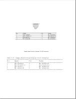
Serial-Ring Indicator
121
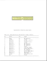
System Address Bit 11
23
Serial Transmit Data
122
System Address Bit 12
24
Serial Clear-to-Send
123
System Address Bit 13
25
Ground
124
Ground
26
Serial Receive Data
125
System Address Bit 14
27
Serial Ready-to-Send
126
System Address Bit 15
28
Serial Carrier Detect
127
System Address Bit 16
29
Serial-Data Set Ready
128
Ground
30
Ground
129
System Address Bit 17
31
DMA Acknowledge 2 *
130
System Address Bit 18
32
DMA Acknowledge 1 *
131
System Address Bit 19
33
DMA Acknowledge 0 *
132
Ground
34
+5V Fused (computer)
133
Printer Select In *
35
Printer Paper Out
134
Diskette Boot
36
Printer Acknowledge *
135
Diskette Low Den. Media *
37
Printer Data Bit 6 *
136
Diskette Direction In *
38
Printer Data Bit 4
137
Ground
39
Ground
138
Diskette Index *
40
Printer Data Bit 2
139
Diskette Change *
41
Printer Data Bit 0
140
Diskette Head Select
42
Keypad Data
141
Ground
43
Battery Voltage
142
Reserved
44
Keyboard Clock
143
No Wait States *
45
Keyboard Data
144
Bus Ready
46
Mouse Clock
145
Ground
47
Battery Voltage
146
I/O Read Control *
48
Ground-CRT
147
I/O Write Control *
49
Ground-CRT
148
ISA Bus Clock
50
Ground-CRT
149
Ground
51
Ground-CRT
150
Address Latch Enable
52
Ground-CRT
151
DMA Cycle Indicator
53
DMA Request 1
152
Unlatched Address Bit 17
54
DMA Request 7
153
Ground
55
DMA Request 6
154
Unlatched Address Bit 18
56
Ground
155
Unlatched Address Bit 19
57
DMA Request 5
156
Unlatched Address Bit 20
58
DMA Request 3
157
Unlatched Address Bit 21
59
DMA Request 2
158
Ground
60
Ground
159
Unlatched Address Bit 22
61
DMA Request 0
160
Unlatched Address Bit 23
62
DMA Acknowledge 7 *
161
System Address Bit 0
63
DMA Acknowledge 6 *
162
Ground
64
Ground
163
System Address Bit 1
65
DMA Acknowledge 5 *
164
System Address Bit 2
66
DMA Acknowledge 3 *
165
System Address Bit 3
67
Spare
166
Diskette Drive Select *
68
Reserved
167
Diskette Low Density *
69
Ground
168
High Density
70
Reserved
169
External Diskette Connected *
71
Diskette Write Protect *
170
Tape Select *
72
Diskette Write Data *
171
Ground
73
Ground
172
Diskette Motor *
74
Diskette Step *
173
16-Bit I/O Cycle *
75
Diskette Track 0 *
174
Low Memory *
76
Reset
175
Ground
77
Ground
176
Memory Read Control *
78
System Data Bit 15
177
Memory Write Control *
79
System Data Bit 14
178
16-Bit Memory Cycle *
80
System Data Bit 13
179
Ground
81
Ground
180
Bus Master Grab *
Summary of Contents for LTE Elite
Page 140: ...7 Remove the hard drive security clips by gently lifting up on them Figure 4 32 ...
Page 248: ...4 Remove the keylock from the outside of the bottom cover Figure 9 5 ...
Page 249: ...5 Slide the plastic keylock barrel out of the bottom cover Figure 9 6 ...
Page 269: ...3 Disconnect the harness extension cable from the system board Figure 9 26 ...
Page 297: ...5 Slide the switch board out of the switch frame Figure 9 52 ...
Page 304: ...5 Replace the eject switch and screw Figure 9 59 ...
Page 309: ...5 Replace the power switch and screw Figure 9 64 ...
Page 348: ...7 Unlock the expansion base keylock Figure D 3 ...
Page 369: ...9 Push the lever toward the back of the convenience base Figure D 16 ...
Page 373: ...5 Slide the computer toward you to remove it from the convenience base ...
Page 387: ......


