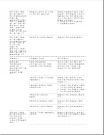
seconds.)
part.
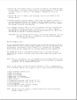
In addition, note that
the first three parts can
be checked by the user.
a. PCMCIA card
b. Battery pack
c. Hard drive
d. Diskette drive
e. Internal AC power
supply
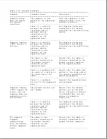
2. Disconnect the display
cable from the system
board and power the unit
up. If the unit powers
up, the display cable or
display assembly has
failed. Plug the display
cable back into the
system board and attempt
to find the defective
part in the display
assembly by completing
the following steps one
at a time until the short
circuit is located:
a. Disconnect the display
cable from the
inverter board and
attempt to power the
unit up. If the unit
powers up, replace the
inverter board.
b. Disconnect the display
cable from the
trackball board and
power the unit up. If
the unit powers up,
replace the trackball
board.
c. Disconnect the display
cable from the display
panel and power the
unit up. If the unit
powers up, replace the
display panel.
d. Replace the display
cable.
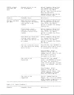
3. Replace the system board.
---------------------------------------------------------------------------
* For information on solving battery problems, refer to Table 2-16.
** The fan turns on and off automatically when the computer reaches certain
temperatures. This is normal.
===========================================================================
Table 2-27. Printer Problems *
Summary of Contents for LTE Elite
Page 140: ...7 Remove the hard drive security clips by gently lifting up on them Figure 4 32 ...
Page 248: ...4 Remove the keylock from the outside of the bottom cover Figure 9 5 ...
Page 249: ...5 Slide the plastic keylock barrel out of the bottom cover Figure 9 6 ...
Page 269: ...3 Disconnect the harness extension cable from the system board Figure 9 26 ...
Page 297: ...5 Slide the switch board out of the switch frame Figure 9 52 ...
Page 304: ...5 Replace the eject switch and screw Figure 9 59 ...
Page 309: ...5 Replace the power switch and screw Figure 9 64 ...
Page 348: ...7 Unlock the expansion base keylock Figure D 3 ...
Page 369: ...9 Push the lever toward the back of the convenience base Figure D 16 ...
Page 373: ...5 Slide the computer toward you to remove it from the convenience base ...
Page 387: ......


